Electro Tech is an online community (with over 170,000 members) who enjoy talking about and building electronic circuits, projects and gadgets. To participate you need to register. Registration is free. Click here to register now.
Welcome to our site! Electro Tech is an online community (with over 170,000 members) who enjoy talking about and building electronic circuits, projects and gadgets. To participate you need to register. Registration is free. Click here to register now.
You should give a few more details on what you hope to achieve, and what you want to use it for. People have been building AM radios at home, from salvaged parts for nearly 100 years. You really should have trouble finding information on how to build one. Search the web, check your local library, retirement home... Use to be ICs that had most everything packed in there except a batterry, speaker, antenna, and a few tunning components. Guess it was mostly an audio amplifiier... Children use to make them for science fair projects, don't think it's very common anymore.
I didn't mean any offense, it's just that you weren't very specific, and there are so many different ways to do this for different results. There are several that require no battery at all. If you have a weak signal, you may want to add an amplifier stage (lots of options here). Output... speakers need an amp, some earphones...
Nearly 100 years ago people made crystal radios to pickup the only AM radio station in their country. They used a very long insulated antenna and an earth ground.Today there are many AM radio stations in each city. An old crystal radio has only a single tuned circuit so it will pickup most of them at the same time.
Besides, the high frequency audio response of an AM radio is horrible. Use an FM radio for good sound.
Nearly 100 years ago people made crystal radios to pickup the only AM radio station in their country. They used a very long insulated antenna and an earth ground.Today there are many AM radio stations in each city. An old crystal radio has only a single tuned circuit so it will pickup most of them at the same time.
Yes.
I made a crystal radio about 105 years ago. It sounded horrible.
I recently tuned my car radio across the AM band to try to find out the score. There were hundreds of AM stations. Luckily the radio has many tuned circuits for good selectivity. It also sounded horrible.
Last month I finally figured out how to get the dash open and remove the radio from my Explorer. It didn't work, because nothing was hooked up. Plugged everything in, and only got cassette and AM. Lots of AM stations, mostly in spanish though.
I found this while surfing....
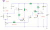
This is a compact three transistor, regenerative receiver with fixed feedback. It is similar in principle to the ZN414 radio IC which is now replaced by the MK484. The design is simple and sensitivity and selectivity of the receiver are good.
All general purpose transistors should work in this circuit, I used three BC549 transistors in my prototype. The tuned circuit is designed for medium wave, but the circuit will work up to much higher frequencies if a different tuning coil and capacitor are used. I used a ferrite rod and tuning capacitor from an old radio which tuned from approximately 550 - 1600kHz. Q1 and Q2 form a compund transistor pair featuring high gain and very high input impedance. This is necessary so as not to unduly load the tank circuit. Q1 operates in emitter follower, Q2 common emitter, self stabilizing bias is via the 120k resistor and the tuning coil.
The 120k resistor provides regenerative feedback,between Q2 output and the tank circuit input and its value affects the overall performance of the whole circuit. Too much feedback and the circuit will become unstable producing a "howling sound". Insufficient feedback and the receiver becomes "deaf". If the circuit oscillates,then R1's value may be decreased; try 68k. If there is a lack of sensitivity, then try increasing R1 to around 150k. R1 could also be replaced by a fixed resisor say 33k and a preset resistor of 100k. This will give adjustment of sensitivity and selectivity of the receiver.
Transistor Q3 has a dual purpose; it performs demodulation of the RF carrier whilst at the same time, amplifying the audio signal. Audio level varies on the strength of the received station but I had typically 10-40 mV. This will directly drive high impedance headphones or can be fed into a suitable amplifier.
I found this while surfing....
This is a compact three transistor, regenerative receiver with fixed feedback. It is similar in principle to the ZN414 radio IC which is now replaced by the MK484. The design is simple and sensitivity and selectivity of the receiver are good.
All general purpose transistors should work in this circuit, I used three BC549 transistors in my prototype. The tuned circuit is designed for medium wave, but the circuit will work up to much higher frequencies if a different tuning coil and capacitor are used. I used a ferrite rod and tuning capacitor from an old radio which tuned from approximately 550 - 1600kHz. Q1 and Q2 form a compund transistor pair featuring high gain and very high input impedance. This is necessary so as not to unduly load the tank circuit. Q1 operates in emitter follower, Q2 common emitter, self stabilizing bias is via the 120k resistor and the tuning coil.
The 120k resistor provides regenerative feedback,between Q2 output and the tank circuit input and its value affects the overall performance of the whole circuit. Too much feedback and the circuit will become unstable producing a "howling sound". Insufficient feedback and the receiver becomes "deaf". If the circuit oscillates,then R1's value may be decreased; try 68k. If there is a lack of sensitivity, then try increasing R1 to around 150k. R1 could also be replaced by a fixed resisor say 33k and a preset resistor of 100k. This will give adjustment of sensitivity and selectivity of the receiver.
Transistor Q3 has a dual purpose; it performs demodulation of the RF carrier whilst at the same time, amplifying the audio signal. Audio level varies on the strength of the received station but I had typically 10-40 mV. This will directly drive high impedance headphones or can be fed into a suitable amplifier.
You didn't build this, did you? I remember commenting on this circuit not too long ago. I can't see how this is regenerative. I don't think the guy who designed it knows what he's talking about.
Please post the link where you found this.
Likewise, the only feedback is DC, decoupled with a 100nF, I'm also dubious about the supposed rectifying properties of Q3, with a 560 Kohm base resistor feed from the collector giving negative feedback.
This site uses cookies to help personalise content, tailor your experience and to keep you logged in if you register.
By continuing to use this site, you are consenting to our use of cookies.

")