Continue to Site

Welcome to our site!

Electro Tech is an online community (with over 170,000 members) who enjoy talking about and building electronic circuits, projects and gadgets. To participate you need to register. Registration is free. Click here to register now.

  • Welcome to our site! Electro Tech is an online community (with over 170,000 members) who enjoy talking about and building electronic circuits, projects and gadgets. To participate you need to register. Registration is free. Click here to register now.

Question about amps

Status
Not open for further replies.

antknee

New Member
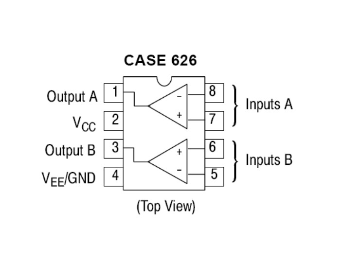
I have the TCA0372 opamp. I'm providing it with 36V from 4 PP3 batteries but all i'm getting on the output is a 50Hz square wave. The load is a 30K resistor, the input from a sig gen with a + offset to take the signal above zero.

I think that if I get the 50Hz output the chip is correctly electrically connected, is that right?

If a chip wants to output 1Amp at 40V like this one unless I can sink 1A from the source, in this case batteries, it'll do not much?

There is no mention in the datasheet of gain, but it does mention the chip is monolithic, does that mean the gain is unity?

Thanks.

tca0372-pins-jpg.43533
 

Attachments

  • tca0372 pins.jpg
    tca0372 pins.jpg
    31.4 KB · Views: 1,085
  • tca0372.pdf
    142.3 KB · Views: 327
It is connected very simply. I think by feedback you are asking if I have grounded the output. I'm inputting at 10KHz.

Thanks.

**broken link removed**
 

Attachments

  • S6308436.JPG
    S6308436.JPG
    43.7 KB · Views: 218
Last edited:
A motor control circuit, for reference.

tca0372-1-gif.43536
 

Attachments

  • tca0372-1.gif
    tca0372-1.gif
    13.4 KB · Views: 875
hi ak,
This configuration from the d/s, is the minimum you require.
 

Attachments

  • AAesp01.gif
    AAesp01.gif
    3.7 KB · Views: 228
Ah I see. Making that up won't be a problem now. Thanks for the simplified version Eric.
 
Last edited:
you think that since its connected in open-loop configuration the AC line is coupling through and causing it to rail at 50Hz?
I thought it was connected w/ batteries? the input is 10kHz
 
you think that since its connected in open-loop configuration the AC line is coupling through and causing it to rail at 50Hz?
I thought it was connected w/ batteries? the input is 10kHz

It's either picking up mains hum, or it's unstable - but open loop it's going to do nothing except bang from rail to rail.
 
I made the circuit up on a stripboard as in the diagram, it works ok. I have a few questions.

I'd like to use the circuit at 100Khz. It's slew rate is 1.3V/us, at this frequency I get the listed peak voltage of about 2V. I can push the voltage up to 10Vpp and the waveform becomes triangular rather than the inputted sine. I could probably live with this waveform but will it cause any other instability?

Where would the decoupling capacitors go and what value should I use?

If I wanted to use a rheostat to change the gain where would it go?

I would like to sink 1Amp from two 9V PP3 batteries, will I get anywhere close, I only need a few minutes from them?

Thanks.

s6308453-jpg.43583
 

Attachments

  • S6308453.JPG
    S6308453.JPG
    43.1 KB · Views: 560
Last edited:
Capacitors from both HT rails to ground, as close to the IC as possible.

1A from small 9V batteries is probably pushing things a lot - but what EXACTLY are you trying to do? - is it still the crazy piezo thing?.
 
I see, thanks. Yes this is an extension of the piezo driver post that is below.

https://www.electro-tech-online.com/threads/replace-10-pp3-batteries-with-4-aaa-batteries.108225/

I'm getting 630mA from the two PP3 batteries, they are rechargeable so I might get a bit more from alkalines.

In my previous incantation I was working in the futurelabs of a multinational PLC with their next generation product. Their product isn't good, its sensational. My intention is to create something similar, patent it, then take prototype and patent to venture capitalists to make a living from developing the product. The drive electronics are difficult for me because I'm a physicist not an electronic engineer. The piezo i'm also making is the clever bit, outside contractors have to make those parts then I put them together and test them. Its not crazy, it is stupidly difficult, if you didn't know the exact technology to use and the end point you just wouldn't attempt it. Failure is a distinct possibility, however nothing ventured nothing gained...
 
Use 10 rechargable AA's in series (for 12V at a pretty high current - FAR more than PP3's), and a normal car 4W amplifier feeding a suitable transformer. If you use a bridged amplifier you can get 16W.

Good luck with your venture, it's pretty unlikely that you can persuade companies to give you money, but a tiny number of people do mange it.
 
I happened to have the TCA0372 so I decided to test it, I have some car ICs on order to try them. I'm really trying to get the number of batteries down because the device needs to be portable and more pocket sized.

I have already tried to get venture capital, I took them information relating to my former employers product and their market research, but despite their reputation it wasn't enough. They said bring us a prototype to look at and a patent, so that is what I'm doing now. It is a long shot but I don't mind the odds.
 
I happened to have the TCA0372 so I decided to test it, I have some car ICs on order to try them. I'm really trying to get the number of batteries down because the device needs to be portable and more pocket sized.

Power takes size, if you need the power then it's diffiuclt to make it small.

I have already tried to get venture capital, I took them information relating to my former employers product and their market research, but despite their reputation it wasn't enough. They said bring us a prototype to look at and a patent, so that is what I'm doing now. It is a long shot but I don't mind the odds.

Certainly a long shot, and expensive to get a patent.
 
The size is a conundrum, I'll have to try to balance it.

I have taken patent advice, applying for a patent is relatively inexpensive, £2000 will get me a UK patent application. Making it worldwide and processing it to grant, which can take 5 years, more like £100,000 and only 1 in 10 applications go to full grant. I can defer applying worldwide for 1 year after the UK patent application, so essentially from the time I apply for the UK patent I have 1 year to pull in funding. Assuming the prototype is good enough that will be enough time. It is hard to predict the future, it is a matter of persisting. There are a ridiculous number of technical and financial difficulties, I look at it like this - the harder it is to do the more valuable it will be should I pull it off.

Thanks for the good luck message. I'll need plenty of luck :)
 
Status
Not open for further replies.

Latest threads

New Articles From Microcontroller Tips

Back
Top