I have a query on constant constant current drivers, specifically the Meanwell LDD-700h driver powering LED's
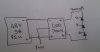
Lets say I have the circuit attached - a 48V PSU supplying power to the LDD (which is a 700mA constant current driver controlled by PWM) which puts out a voltage from 2-56V (from the datasheet)
Now I hook up 3 power LED's with a forward voltage of 3V at 700mA.
I get the LDD can drive the LED's at 700mA but each LED has a voltage of 3V - 9V in total.
If I connect the LDD wont it supply a voltage of 48V to the LED's - how does the LDD know that I only have 3 LEDs and that it must only supply a max of 9V. Is that controlled by the PWM? If so I could potentially put 48V across the LED's by messing around with the PWM?
https://www.electro-tech-online.com/custompdfs/2013/06/LDD-H-spec.pdf
BTW I"m going to control the PWM using an Arduino.