Electro Tech is an online community (with over 170,000 members) who enjoy talking about and building electronic circuits, projects and gadgets. To participate you need to register. Registration is free. Click here to register now.
Welcome to our site! Electro Tech is an online community (with over 170,000 members) who enjoy talking about and building electronic circuits, projects and gadgets. To participate you need to register. Registration is free. Click here to register now.
The Q-point is simply the DC operating point or DC biasing point for the transistor circuit. Typically, DC biasing conditions are set up to place the transistor and supporting circuitry in a condition that makes it useful, and no other signals (such as AC signals or swiching signals) are relevant when you consider the Q-point. Typcially, an AC signal or some other dynamic change (such as a switching event) is then applied. Sometimes the a small AC signal is applied and the circuit never deviates far from the bias point. However, if large dynamic changes are made, then the circuit variables change significantly from the Q-point.
So generally, with nonlinear circuits, with transistor circuits being a good example, we analyze the circuit first from the point of view of DC only and try to establish a Q-point. Then, we consider the dynamics around that condition. For small AC signals, we can create a linearized model of the system, and the linearization takes place at the conditions of the Q-point.
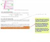
In the example you show, the Q-point is going to be at the intersection of the load line curve and the transistor curve for the Vgs condition you set up. The highlighted text is considering this fact and noting that if the Vgs is raised sufficiently that the transistor "resistance" is small compared to the load resistance, the actual value of Vgs does not significantly change the Q-point. You can see this in the figure which shows the dot on the load line on the left near the I_D axis. This is just a fancy way of saying that you turned the transistor fully on, and most of the supply voltage is on the load. Once the transistor is nearly fully on, driving it harder with large Vgs does not move the Q-point all that much.
The threshold voltage of a silicon diode is 0.7V and this is the voltage which drops across a diode. Now consider an E-MOSFET transistor which always has positive threshold voltage, V_th. Let's say V_th=0.7V. Will this 0.7V drop across the transistor in order for it to conduct? Note that the transistor will also need a certain V_ds in order to conduct. Let's assume to conduct 230μA the transistor needs V_ds=2V and has V_th=0.7V, then would this mean that the transistor needs total of 2.7V in order to conduct this current through it? Personally, I don't think V_th is the voltage which drops across a transistor; it's just the voltage which tells us that V_gs should be greater than V_th in order for it to conduct, and the only voltage drop which occurs is the V_ds one. Could you please help me with this? Thank you.
The threshold voltage of a silicon diode is 0.7V and this is the voltage which drops across a diode. Now consider an E-MOSFET transistor which always has positive threshold voltage, V_th. Let's say V_th=0.7V. Will this 0.7V drop across the transistor in order for it to conduct? Note that the transistor will also need a certain V_ds in order to conduct. Let's assume to conduct 230μA the transistor needs V_ds=2V and has V_th=0.7V, then would this mean that the transistor needs total of 2.7V in order to conduct this current through it? Personally, I don't think V_th is the voltage which drops across a transistor; it's just the voltage which tells us that V_gs should be greater than V_th in order for it to conduct, and the only voltage drop which occurs is the V_ds one. Could you please help me with this? Thank you.
The wording in your question is not entirely clear. When you say "drop across the transistor", what does this mean? There is a Vgs and a Vds, so there are two drops that are relevant. There is even a third drop (Vgd), but this is determined by the other two voltages and usually not talked about. The Vgs is the control voltage, and this voltage needs to be above Vth in order to get appreciable current in the load side. The Vds does need to be above a certain value for many circuit topologies, but this is a very small voltage and mostly independent of the gate voltage (actually determined by the Rds resistance) and Vds can certainly be less than the Vgs. Remember that once current start to flow through the load resistor, Vds goes down, and once the transistor is fully on, Vds can be small, even though Vgs would be relatively large to turn the transistor on. So, think of these voltages as independent usually.
There are similarities between bipolar transistor circuits and E-MOSFET circuits and usually the same topology works for either, even though the design equations are different. You are correct that Vth is not the actual drop on the gate side of the device, which is different than the bipolar transistor which usually has Vbe ~ 0.7 V over a wide range of drive conditions. This is a key difference that sometimes makes people call the bipolar transistor a current controlled device, and the FET a voltage controlled device. This is a bit of an illusion because the Vbe is also changing on a logarithmic curve (inverse of exponential). Still, when circuits are dealing with many tens of volts and Vbe is changing by tenths of volts, a designer is going to treat Vbe as a constant for design purposes.
Anyway, there is value in comparing bipolar and E-MOSFET transistor circuits, but always remember they are made with different devices with their own characteristics and equations.
Just a quick note to explain the expression "Q-point".
When a circuit (typically an amplifier) is at rest, ie not processing any signal, there is a standing current.
This standing current has traditionally been referred to as the "quiescent current" and so from this the term Q-point has developed to describe where the device is biased.
This site uses cookies to help personalise content, tailor your experience and to keep you logged in if you register.
By continuing to use this site, you are consenting to our use of cookies.