Continue to Site

Welcome to our site!

Electro Tech is an online community (with over 170,000 members) who enjoy talking about and building electronic circuits, projects and gadgets. To participate you need to register. Registration is free. Click here to register now.

  • Welcome to our site! Electro Tech is an online community (with over 170,000 members) who enjoy talking about and building electronic circuits, projects and gadgets. To participate you need to register. Registration is free. Click here to register now.

PWM using software AtoD

Status
Not open for further replies.

jeremygaughan

New Member
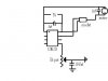
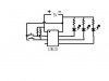
My project is to build an infrared RC system for indoor airplanes. Many have done it before that I could copy, but I want to learn to program. What I'm did first was learn to create PWM in software using a simple circuit. Then I put a potentiometer into the circuit to adjust the speed of the motor/force of a coil "BIRD" actuator. Later I will learn how to send the information over IR. The issue that I have is that the motor is not changing speeds when I adjust the potentiometer. I suspect that I am using the addlw improperly. The idea is to subtract the value read from the capacitor discharge time from 255 and get the bit high and bit low times of my bit-bang style PWM. I have included a drawing of the circuit and my code.
Code:
;PWM project
	list P=12f629
#include <p12f629.inc>
	__config _INTRC_OSC_NOCLKOUT & _BODEN_OFF & _WDT_OFF & _PWRTE_ON & _MCLRE_OFF & _CPD_OFF & _CP_OFF 
	ERRORLEVEL -302
	
	cblock		20h
	AV,BH,BL,DELAY
	endc

	ORG		0000h		;start here on powerup
	goto	START		;skip interrupt location
	ORG		0004h		;interrupt location
	goto	AVinterrupt	;duh
	bcf		INTCON,2	;reset interrupt flag to 0
	RETFIE
START
	movlw	0x07		;turn off comparitors
	movwf	CMCON
	
	bsf		INTCON,7	;global interrupt enabled
	bsf		INTCON,5	;set timer interrupt

	bsf		STATUS,RP0	;switch to bank 1
	movlw	0x02		;set prescaler
	movwf	OPTION_REG	;put in option register
	movlw	0x00		;set pins I/O
	movwf	TRISIO		;put value in tris
	bcf		STATUS,RP0	;switch back to bank 0
PWM	
	addlw	0xFF-AV	;determine time to keep bit high
	movwf	BH
	movlw	0x07	;set output bit high
	movwf	GPIO
loop1
	decfsz	BH,f	;keep output bit high 
	goto	loop1
	movlw	0x04	;set output bit low
	movwf	GPIO	
loop2
	decfsz	AV,f	;keep output bit low for the rest of the 256
	goto	loop2
	goto	PWM
	
AVinterrupt
	bsf		STATUS,RP0	;set pin to input
	movlw	0x04
	movwf	TRISIO
	bcf		STATUS,RP0

	clrf	AV			;clear
	
AVloop
	incf	AV,1		;add one for every time the following test results in pin still high
	btfsc	GPIO,2		;test if pin still high
	goto	AVloop

	bsf		STATUS,RP0	;set all to output
	movlw	0x00
	movwf	TRISIO
	bcf		STATUS,RP0
	return
	
	end
 

Attachments

  • PWMCIRCUIT.JPG
    PWMCIRCUIT.JPG
    12.9 KB · Views: 446
Not sure if you need it but your code does not save the W & STATUS on interrupt.
Also you must wait a small amout of time for the A/D to setup before you use it.
 
What I have done to keep from waiting for the cap to charge in the interrupt code is I leave the bit high all the time so the cap should be charged all the time until I want to read it in my interrupt. Maybe I should make my prescaler bigger to wait longer?
I think I should save the W value. Does this sounds right....I should save it because if the interrupt cuts in right when I'm in the middle of a high or low of the PWM it will finish the cycle with the value 255 instead of what I had there.
 
Yes save both the W and STATUS registers.

Here's some food for thought.
When you need A/D or PWM choose a PIC that has them in hardware rather than doing it in software, it's so much easier. The 12F683 has both.

Check the Toy Car project on my site to see A/D & PWM code for a 16F88.
 
I think it would be easier with hardware, but I want to implement up to 4 channels later on. With small SMD PICs I think I need to have the PWM in software to get that many channels. Also I'm simply interested in how to make it happen using a program.
So, what I have found is if I hold the pin where the pot is high or low it makes no difference in my motor speed. It should at least be all off or all on with that change. For some reason my value is not making it to the PWM cycle.
 
Last edited:
I agree, I'm more interested in learning to write the PWM and the IR code. The AtoD will be a lot more accurate done in the hardware. When I have the revised code for the 12f675 written I'll post it. Also what command saves the w and status registers?
 
You need to assign them to two variables, here's some sample code from Peter Andersons site.
https://www.phanderson.com/PIC/16C84/interrupts/interrupt_1.html
Code:
INT_SERV:
     MOVWF W_SAVE        ; save W
     SWAPF STATUS, W     ; save STATUS 
     MOVWF STATUS_SAVE
     BCF STATUS, RP0     ; be sure we are in bank 0
; your stuff goes here  

; and finishes here.
     BCF INTCON, INTF    ; indicate that interrupt has been serviced
     SWAPF STATUS_SAVE, W
     MOVWF STATUS    ; restore W and STATUS
     SWAPF W_SAVE, F
     SWAPF W_SAVE, W     

     RETFIE
 
I decided I've started a little too big. So I broke my code into two parts; PWM and AtoD. I'm ready to code now but now my PICKIT 2 is acting crazy. It recognizes the chip and then can read it....then when I try to program suddenly it says no device detected. If I unplug it and replug it again it will recognize the pic but when I try to do anything to it it says again no device detected. Anyway, here is the code for the PWM bit-bang. The idea is to change the brightness of a LED when I bring a pin high. I'm using a LED instead of a motor to make the circuit simpler and easier to problem solve.
Code:
#include <p12f629.inc>
	__config _INTRC_OSC_NOCLKOUT & _BODEN_OFF & _WDT_OFF & _PWRTE_ON & _MCLRE_OFF & _CPD_OFF & _CP_OFF 
	ERRORLEVEL -302
	
	cblock		20h
	BH,DELAY
	endc
	
	bsf	STATUS,RP0		;bank 1
	movlw	0x30
	movwf	TRISIO		;make bit 4 and 5 inputs
	bcf	STATUS,RP0
	
start
	movlw	0x00		;set BH to zero
	movwf	BH
	call	bithigh		;call to check if pin is high
	call	bitlow		;call to check if pin is high
	movlw	0x01		;turn led on
	movwf	GPIO
	
loop
	decfsz	BH,1		;count down time to keep led on
	goto	loop
	movlw	0x00		;turn led off
	movlw	GPIO
	
	movlw	0x00		;check again if pins are high
	movwf	BH
	call	bithigh
	call	bitlow

loop2
	incfsz	BH,1		;count up to keep led off
	goto	loop2
	goto	start
	
bithigh
	btfss	GPIO,4		;test pin to see if high
	return
	movlw	0x88		;if high make BH about half of 256
	movwf	BH
	return

bitlow
	btfss	GPIO,5		;test if pin high
	return
	movlw	0xff		;if high make BH 256
	movwf	BH
	return
	
	end
 
When using 12f629 and setting the program pin to out put there are problems entering program mode. In the menu bar >tools >VPP first program entry works most of the time. So pickit 2 problem mostly solved, now my program..... This is what happens with my PWM test program. It lights the led about half way when powered up. If I bring pin 6 or 7 high the led turns off instead of changing brightness. Any ideas about what I can change in my program?
 
jeremygaughan said:
If I bring pin 6 or 7 high the led turns off instead of changing brightness. Any ideas about what I can change in my program?

You code sets pins 2 & 3 to input - not 6 & 7. I find it confusing when people refer to pin numbers, much better to refer to IO/Port numbers.

Mike.
 
I'll use bits next time to describe the process. So after a little homework I got my PWM to work, and even threw in a few inputs. The first thing I learned is that an input that is driven low to activate needs to be held high with a resistor in the mean time. Here is the circuit and the working code for any newbies like me that want to see.
Code:
;PWM simple
	list P=12f629
#include <p12f629.inc>
	__config _INTRC_OSC_NOCLKOUT & _BODEN_OFF & _WDT_OFF & _PWRTE_ON & _MCLRE_OFF & _CPD_OFF & _CP_OFF 
	ERRORLEVEL -302
	
	cblock		20h
	BH,BL,DELAY
	endc
	
	bsf	STATUS,RP0		;bank 1
	movlw	0x30
	movwf	TRISIO		;make bit 4 and 5 inputs
	bcf	STATUS,RP0
	
	movlw	0x07		;turn off comparitors
	movwf	CMCON
	
Start           
	movlw	0x00		;turn leds off
	movwf	GPIO
test
	btfss	GPIO,4		;test for bit 4 low
	call	dim			;if low goto dim pwm
test2
	btfss	GPIO,5		;test if bit 5 low
	call	bright		;if low goto btight pwm
	goto	Start
	
dim
	movlw	0x04		;set on time of duty cycle
	movwf	BH

loop
	decfsz	BH,1		;count down the on time
	goto	loop
	movlw	0x00		;turn leds off
	movwf	GPIO
	
	movlw	0x04		;set off time of duty cycle
	movwf	BH

loop2
	incfsz	BH,1		;count up to the off time
	goto	loop2
	movlw	0x07		;turn leds on
	movwf	GPIO
	goto	test		;repeat until bit high
	
bright
	movlw	0x10		;set on time
	movwf	BH

loop3
	decfsz	BH,1		;count down time to keep leds on
	goto	loop3
	movlw	0x00		;turn leds off
	movwf	GPIO
	
	movlw	0x10		;set off time
	movwf	BH

loop4
	incfsz	BH,1		;count up to keep leds off
	goto	loop4
	movlw	0x07		;turn leds on
	movwf	GPIO
	goto	test2		;repeat until bit high

	end
 

Attachments

  • PWMTEST.JPG
    PWMTEST.JPG
    11.6 KB · Views: 226
Last edited:
Status
Not open for further replies.

New Articles From Microcontroller Tips

Back
Top