Continue to Site

Welcome to our site!

Electro Tech is an online community (with over 170,000 members) who enjoy talking about and building electronic circuits, projects and gadgets. To participate you need to register. Registration is free. Click here to register now.

  • Welcome to our site! Electro Tech is an online community (with over 170,000 members) who enjoy talking about and building electronic circuits, projects and gadgets. To participate you need to register. Registration is free. Click here to register now.

PWM Signal Repeater for Inductive DC Load

Status
Not open for further replies.

MikahB

New Member
Hi guys, new to the forum and new to circuit design. I'm a mechanical engineer and recently came upon a need that seems like a good opportunity to expand my electrical work beyond just wiring cars.

I need to add a second motor to an vehicle where the existing motor is driven from an OEM control module (it's a vehicle LAN network node and implements closed-loop control logic). The output from the OEM controller is a 0-12.0V PWM signal and the controller is rated at 15A continuous and 30A max.

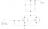
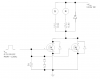
I thought I could use the existing output signal as a gate driver for a pair of parallel N-channel MOSFETs to step up the current capacity to double (at least) that of the OEM controller. I have already verified through experimentation that the control logic will handle the second motor, I just need to be able to drive it safely.

Attached is the circuit diagram I've come up with. I've also been looking at candidates for the MOSFETs and the IXFE48N50Q from IXYS looks promising. First question, though, is am I on the right track with the circuit design?

I appreciate any information or feedback you can provide and look forward to learning more about circuits.
 

Attachments

  • pump_signal_booster_v1.1.png
    pump_signal_booster_v1.1.png
    41.4 KB · Views: 174
I need to add a second motor to an vehicle where the existing motor is driven from an OEM control module (it's a vehicle LAN network node and implements closed-loop control logic).

This kind of implies 2 directions. Is it bi-directional?
the IXFE48N50Q from IXYS looks promising.
You could use a FET rated at 100 volts and save a few $.
First question, though, is am I on the right track with the circuit design?
Your diode should be across the motor with the cathode to +13.6 V.
 
Hi Ron, thanks for the input. Couple answers to your Q's

- No, the motor is not bi-directional. It is a variable-speed pump.
- That was to be one of my next questions - the value of a pair of smaller FETs in parallel versus a single, larger unit. These IXYS FETs are actually rated for 500V Vdd and 39A continuous load. So, I could use a slightly bigger one and be okay, just wasn't sure which would be more efficient - the cost per FET is low enough that I'm fine with two.
- 10-4 on the flyback diode, I'll update my diagram to reflect.
 
Just one problem that I see. Without a respective resistor (say ~ 0.1 ohm) in series with each FET source to balance the load, one FET will probably hog the current (because of manufacturing tolerances) and fail, followed shortly after by failure of the other FET!
 
.....oh, and with that hefty load perhaps causing voltage spikes it may be an idea to provide two zener diodes connected in series back-to-back between the FET gates and ground.
 
Thank you Ron and Alec, I really appreciate it. Hopefully I've got the resistors inline with the loads properly now and my flyback diode across the proper points. I did some more reading on the topic and I think I get the idea now - please let me know if I'm still not getting it.

Alec, I added the anti-series Zener Diodes you mentioned and read up on the topic - I was not aware that a voltage spike could feed back from the drain through the gate, but now that I am aware it makes sense that you need to give a path to dissipate the power from such a spike.

Thanks again for the input - greatly appreciated.
 

Attachments

  • pump_signal_booster_v1.2.png
    pump_signal_booster_v1.2.png
    42.2 KB · Views: 167
The FETs will naturally share the current, the one with the most current heats up and becomes more resistive thereby sharing the current to the other device. The 0.1 ohm resistors are not really necessary. What would be good though is some fusing in the supply side, it won't save the fets but will protect against shorts.
Also a fast snubber between the drain and the source of the fets, something to absorb the fast spike energy. The high current diode across the motors might not be fast enough. This snubber should be physically as close to the FETs as possible to cut down on leakage inductance.
Also a very small resistor or ferrite bead in series with and right next to the respective gates will stop any VHF oscillations. A couple of ohms is fine.
 
@MikeahB
That's the circuit I had in mind.
@Moffy
Agreed, provided the chosen FETs are suitably rated . But I'd rather not risk 'the one with the most current heats up'. In another thread on this forum a guy watched (heard?) his paralleled FETs pop one after another in the absence of the series source resistors!!
I second your suggestions re the fuse, snubber etc.
 
Thanks moffy for the input. The source voltage will be through a fusible link, probably 50A. Are the diodes I have across the source/drain already not acting as the snubbers? In fact, the FET's I'm looking at have that diode built in - is it likely for the purpose you're suggesting here? (datasheet attached)

10-4 on the anti-VHF thoughts. I've seen the resistors mentioned many times with a variety of recommended resistances. I will include small resistors right at the gate on each FET to avoid this oscillation. The reason I excluded them was that neither of my sources are high frequency, but doing more reading it looks like that may not be relevant anyway.

Again, I appreciate all the input. Looks as though we may be building a test circuit soon - I will let you know how it goes.
 

Attachments

  • ixys_N-FET_98985.pdf
    553.5 KB · Views: 235
For a mechanical engineer you seem to have a pretty good idea of electronics, much better I'm sure than my understanding of mechanics.
The body diodes of the FETs (they are a side effect of the manufacturing process) would not snub positive going voltages. With the fast rise times of FETs you can get very high spike voltages on the drain, which tend to cause catastrophic failure. The snubber has usually a very fast diode a capacitor and a discharge resistor.

You should save some money and choose lower voltage devices as ronv suggested say 100v.
Since you also have 2 motors, instead of parralleling you could have 1 FET per motor.

Anyway best of success.
 
I appreciate that moffy, but I am very inexperienced with electronics. I've wired up lots of race cars, but a relay has been the most advanced component I've worked with integrating before. I do enjoy a challenge, however, and there is a LOT of information available online when you have a specific need like I do now.

10-4 on the snubbers, that makes sense. I have been looking for a lower cost/lower voltage FET to use but I can't find one with an appropriate continuous drain load (30A min) and/or power rating (360W min) that is not super high voltage. I'll do some more looking as I've mostly been on digikey, maybe I'm just missing something.

Ordering parts today and have a car here to test on this week - should be interesting!

EDIT: One more thing, there is a physical limitation that neccesitates the parallel to single conductor to parallel setup, otherwise I'd love to have an FET per motor.

For a mechanical engineer you seem to have a pretty good idea of electronics, much better I'm sure than my understanding of mechanics.
The body diodes of the FETs (they are a side effect of the manufacturing process) would not snub positive going voltages. With the fast rise times of FETs you can get very high spike voltages on the drain, which tend to cause catastrophic failure. The snubber has usually a very fast diode a capacitor and a discharge resistor.

You should save some money and choose lower voltage devices as ronv suggested say 100v.
Since you also have 2 motors, instead of parralleling you could have 1 FET per motor.

Anyway best of success.
 
Last edited:
Pity. If you decide to use current sharing resistors there should be 1 per FET not 1 per motor. Also 0.1ohm is excessive.
Where did you get the 360W figure? Suitable FETs should dissipate well under 100W each probably even 50W e.g. 0.1R*20A*20A = 40W and that should be a high figure as the FETs you could choose would have a much lower Rdson. The losses due to switching should be fairly low as I'm assuming a frequency below 1kHz.
 
Discovered earlier today that I had been misreading the "Max Power" column on Digikey. I thought it mean maximum continuous throughput power, not power dissipated. So, that's where I was getting my 360W.

But yes, once I figured that out I found some more reasonably sized FET's that should work well. 10-4 on current sharing resistors per FET, that is actually preferable since it means I can contain them within the unit. I will downsize the resistors too to get less power dissipated.

Found a good document on sizing snubbers and flyback diodes, going to read through that tomorrow.

Thanks again, really appreciate all the help.
 
Status
Not open for further replies.

New Articles From Microcontroller Tips

Back
Top