Continue to Site

Welcome to our site!

Electro Tech is an online community (with over 170,000 members) who enjoy talking about and building electronic circuits, projects and gadgets. To participate you need to register. Registration is free. Click here to register now.

  • Welcome to our site! Electro Tech is an online community (with over 170,000 members) who enjoy talking about and building electronic circuits, projects and gadgets. To participate you need to register. Registration is free. Click here to register now.

PWM on a LOW Pass Filter

Status
Not open for further replies.
Actually a good question. I don’t know what residual ripple is & never heard.

The frequency of course I have to calculate. What’s the best frequency will it suits?

Thanks

dc1-jpg.20118


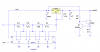
The graphic you used in this post is the way you want to do it. Connect the RC lowpass to the ADJ pin (point A connects to the ADJ pin, point B connects to ground). Use a 121 ohm resistor between OUT and ADJ.

The LM317 will fight to keep 1.25V between OUT and ADJ, so OUT will always be 1.25V above ADJ. Residual Ripple is the fact that the PWM signal will not be perfect DC but will have some of the PWM content on it at very low amplitude. It will look like little spikes at the switching frequency of less than 100mV on top of the DC output of the lowpass filter. This noise will translate directly onto OUT since the LM317 will just add 1.25V to whatever is on the ADJ pin.

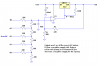
Now, if you are using a 0-5V PWM signal, you will only be able to get 6.25V out of the regulator. You will need to apply gain to the signal if you want to get higher voltages. I suggest that you do this with an op amp configured as a second-order lowpass filter (better performance and less ripple induced from the PWM signal to the OUT voltage) with the gain factor that you need (kill two birds with one stone).

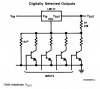
You are DONE. Do not waste data lines for 12 transistors and all that. Use the PWM.
 
Last edited:
Hi I also earlier planned to use different resisters to ADJ pin via different transistors.
Like in the national datasheet.

But if I need 12 values I need 12 transistors? Oh no I don’t like that.

That’s why I need a LPF method driven by a PWM output.

The problem is still I don’t know how to connect the LPF to the LM317T.


Actually a good question. I don’t know what residual ripple is & never heard.

The frequency of course I have to calculate. What’s the best frequency will it suits?

Thanks
To get 12 values, you need four control inputs (4 resistors), which will give you 16 different possible output voltages.
If you use filtered PWM, you will get ripple. This is an unavoidable consequence of filtering a pulse waveform. The amount of ripple you get can be a small as you want. The lower the ripple, the more time it will take to settle when you switch to a new voltage. For fastest settling time, you should make the PWM frequency as high as possible, since this will allow you to use a filter with a shorter time constant.
 
I guess its better to do it with the transistor method. Means 0 setting times and 0 noise. And to get a reasonable resolution not that much of then is needed. If you have that much other stuff on it you can always get a bigger microcontroller.
 
The four-resistor circuit as I think we were imagining it turns out to be more complicated than we thought. In order to get equal-sized steps, the resistors have to be in series, but the switches have to short each one out individually. See below.
If anyone has a simpler scheme, please post it.
I have added a circuit using a simple resistor DAC with an op amp buffer.
 

Attachments

  • 4-bit DAC with LM317.PNG
    4-bit DAC with LM317.PNG
    28.9 KB · Views: 778
  • 4-bit DAC1 with LM317.PNG
    4-bit DAC1 with LM317.PNG
    16.9 KB · Views: 892
Well it is a lot simpler. You simply drive the transistors with the pics output pin. If he needed only up to 6V even the transistors could be lost and replaces by the direct connection to the PICs pins.

Here 4 bit acuray is used that mean you have 16 different voltages selectable. If you use 8 you get a big 256 different values. It just doubles with every extra bit.

EDIT: Oh and this is from the LM317 datasheet by National Semi. page 18
 

Attachments

  • 435354564.PNG
    435354564.PNG
    19.2 KB · Views: 548
Last edited:
Well it is a lot simpler. You simply drive the transistors with the pics output pin. If he needed only up to 6V even the transistors could be lost and replaces by the direct connection to the PICs pins.

Here 4 bit acuray is used that mean you have 16 different voltages selectable. If you use 8 you get a big 256 different values. It just doubles with every extra bit.

EDIT: Oh and this is from the LM317 datasheet by National Semi. page 18
The National circuit will work fine for four output levels, but I don't think you can combine them in binary fashion to get equally spaced steps. I didn't try all combinations of resistor values (only binary ratios), but I think the steps will be sort of logarithmically spaced. Do some simulations or calculations before you jump to any conclusions.
 
The National circuit will work fine for four output levels, but I don't think you can combine them in binary fashion to get equally spaced steps. I didn't try all combinations of resistor values (only binary ratios), but I think the steps will be sort of logarithmically spaced. Do some simulations or calculations before you jump to any conclusions.

I had a play in excel and you are correct that the steps aren't linear but with the right resistors the required 12 voltages may be possible. Sheet attached, zipped as xls not allowed.

Mike.
 
Last edited:
Hi guys thanks for the help.Thats what I needed.

I like to build Rons circuit that opamp thing.I understood that .But I'm having difficulties calculating the input 4 resisters.This weekend I'm going to study it.

After knowing the correct concept I like to build the LPF method also.A non linear output voltages also a problem.Mikes graph showed them.
 
The way to do it would be to make an R2R network to feed the opamp. This makes things easier as far as finding resistor values goes:
Resistor Ladder - Wikipedia, the free encyclopedia
The Wiki page shows you how to calculate the output voltage steps of the R2R ladder. You could use the standard 1% resistor values of 10K and 20K for the ladder. Then you would adjust the gain of the opamp circuit so that you get 0.5V steps.
For example, if you built the 5 bit R2R network, the step would be 0.15625V if running the PIC from a 5V supply. So you would need to set the gain of the opamp circuit to 3.2 for 0.5V steps on the output.
 

Attachments

  • 5-bit DAC1 with LM317.PNG
    5-bit DAC1 with LM317.PNG
    21.4 KB · Views: 477
Last edited:
Status
Not open for further replies.

Latest threads

New Articles From Microcontroller Tips

Back
Top