I want to build a little RC car. It will be a breadboard project so I would like to minimize wiring. Does anyone know a nice PWM IC where you can input a control voltage and get out PWM from 0 to 100%? It would be nice if it could run off 12 volts, but not a must.
Continue to Site
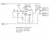
") , makes for a budget RC tank.
, makes for a budget RC tank.