Continue to Site

Welcome to our site!

Electro Tech is an online community (with over 170,000 members) who enjoy talking about and building electronic circuits, projects and gadgets. To participate you need to register. Registration is free. Click here to register now.

  • Welcome to our site! Electro Tech is an online community (with over 170,000 members) who enjoy talking about and building electronic circuits, projects and gadgets. To participate you need to register. Registration is free. Click here to register now.

PWM/ADC code/schematic, working in sim, not in when hooked up.

Status
Not open for further replies.

MoRoH

New Member
OK,

I want my PIC16F873A to take in 0 to 5vdc, it will output a 10bit adc number where 0v = 0000000000 and 5V = 1111111111. It will also output a PWM wavefrom where 0v = 0% dutycycle 2.5v = 50%duty and 5v = 100%duty.


ADC and PWM both work on simulator

PWM output on CCP2

10 bits numers on RB0-RB7 and 2 MSB on RC6 and RC7

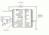
when i hooked it up it does not work, here is my a basic schematic of what is hooked up

:confused:

Code:
unsigned int duty_cycle;      //
unsigned int adc_val;


void InitMain() {

  ADCON1 = 0xfe;                     // All ADC pin 1 to on
  TRISA = 0x01;                      // PORTA is input

  TRISB  = 0x00  ;                   //Set Port RB0-RB7 to LSB


  TRISC  = 0x3F;                   // Pins RC7, RC6 are outputs MSB


  PORTC = 0;                      // intitialize port C to 0

  Pwm_Init(5000);                // Initialize PWM module

                                // Timer 2
   PR2=62;
   T2CON = (1<<TMR2ON);

                                     // Initialize Control PWM
   CCPR1L  = 50;                     // Initial Duty
   CCP1CON = 0x0f;                   // PWM mode set and 5,4 duty = 0
}

void main() {
  InitMain();
  Pwm_Start();                       // Start PWM

while (2)                            //Start while loop
{

    adc_val = adc_read(0)    ;
    portb = adc_val     ;
    portc = adc_val >> 2;            // Send 2 most significant bits to Rc7, Rc6


 adc_val = adc_read(0);              //read analog input RA0
    duty_cycle=adc_val*64;	     // CALIBRATED IT BY CHANGIN 100 TO 64
    duty_cycle/=1024;
    CCPR1L  = duty_cycle;
}
}
 

Attachments

  • PIC16f873a.gif
    PIC16f873a.gif
    15.3 KB · Views: 495
You'll need a 0.1uF decoupling cap across VDD & VSS

What are your config values? HS, XT etc...

What did you program it with? LVP or HVP?
 
Last edited:
Hey,

I set the oscillator type to XT and i also tried HS..i'm not sure what to use i Have a 8MHz crystal.

I will put a decoupling cap between VDD and VSS tommorow

If by HVP or LVP you mean hig voltage program or low voltage program, i used high voltage program.
 
Do i need a delay (200ms) type command at the end?
 
Try putting and LED on one of the pins and then when your program your code so that the led turns on as soon as possible. If it does, try changing the position of where your led turns on or off. It will kind of give you an idea where the problem may lie if it is a software related issue. Poor mans debugger =)

Also, might be stupid, but I know that some simulators dont nessarily include vdd and vss connections. You DO have 5V externally connected to both VDD and gnd connections to all VSS ?

A problem which i encountered is if your fuses are not set up properly. Make sure that you are using XT and that WDT is disabled.

But try the led thing, it might give you some insight.
 
Ok i will give that a try.

I have 5V on Vdd and VSs to gnd. I have 0-5vdc goign in a was just using a voltmeter on the ADC output to see if i could get a high and a scope on CCP1 but not luck.

Thanks
 
1/2 working

Hello,


I came in today, put the a 1uF cap from VDD to VSS, turned my power on and then put a voltmeter on the output pins and the ADC works..ALL 10bits..:)

BUT

The pwm does not work..:(.I have an 8MHZ clock and my PWM i set to 5KHz.. Would i be able to lock on to that signal off C2 with a scope? wouldint i need a refrence/5KHz clk?

I'm thinking i might need to add a delay_200ms command..im goona try that because all other PWM code i saw included that..any other suggestions are welcome.:confused:


Thanks alot
 
Ok, it was fully working well, then i reconnected the circuit and now...it onlt works when i take the crystal out and put it backl ...it reads the vvalue and displays it.

it only changes when i take the crystal out and put it back it..it will not do it on its own?

any idea?
 
Update for those of you who care:

I think i got it working now...i re-programmed the chip using HS instead of XT and turned the rigth fuses on and off..well see how long it last this time.
 
I have it working, but for some reason when the motor turns on at like 2v all the LED's come on for the ADC. it works fine before the motor comes on then they all come on when the motor turns on? and guesses why?
 
hai i`m new guys here

i`m finding ways to convert ADC from sensor to PIC18F452 output is Analog PWM to motor.
can anybody help me?
thanks very very much
 
Status
Not open for further replies.

Latest threads

New Articles From Microcontroller Tips

Back
Top