Continue to Site

Welcome to our site!

Electro Tech is an online community (with over 170,000 members) who enjoy talking about and building electronic circuits, projects and gadgets. To participate you need to register. Registration is free. Click here to register now.

  • Welcome to our site! Electro Tech is an online community (with over 170,000 members) who enjoy talking about and building electronic circuits, projects and gadgets. To participate you need to register. Registration is free. Click here to register now.

Puzzled about a telescope drive

Status
Not open for further replies.

BrokenScope

New Member
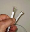
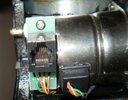
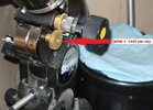
I have an older 8" orion telescope that only has a polar (right ascension) drive on the mount. It lost its control box somewhere between yard sales. I was told it has a 6v servo motor that needs that box with some controls. I don't know where to get them or how to properly assemble them. I've attached some pics which may be helpful. Best2u and thanks
 

Attachments

  • 6 connectors.JPG
    6 connectors.JPG
    71.1 KB · Views: 191
  • RPM.JPG
    RPM.JPG
    142.8 KB · Views: 193
It may be a stepper motor. I would check the resistance between each of the wires. If there are two pairs of wires with the same resistance between each pair, and no continuity between pairs, it would most likely be a stepper motor. It's quite possible that only 4 connections of the 6 way connector are used.
 
From what I can find, they are a small bipolar stepper, as Diver says.

This looks like it may be useful - a DIY universal controller:

 
Interestingly, 1440 revs per day is 1 rev per minute so it will rotate at the same speed as the second finger on a clock. So if the motor is 200 steps (standard stepper motor) then you'll need a step every 300mS.

Mike.
 
I could get the control box from the company if they didn't have such poor business practices. All I really need is a motor that turns at 1/10th RPM. Anyone know where I can get that ?
 
I believe you need the proper variable speed control system, as according to the manual for the motor drive, that becomes the only way of rotating the mount?
(The manual knob is not supposed to be refitted).

In general, a motor geared down enough to turn smoothly with such a low output speed will not be able to back-drive through the gearbox. Also, a simple DC motor would not have stable enough speed control for accurate tracking.

A stepper controller such as I linked to above is very simple and cheap, eg. just a suitable Arduino board plus a stepper driver module, and load the free firmware.

The author of that included a photo of a test setup - an Arduino mega and a little driver board>

onstep_testing.jpg
 
I'd like something simpler. What about a very slow AC timing motor with a light dimmer switch ? The one shown is a 6 RPH, but there are other speeds as shown on Herbach and Rademan.
 

Attachments

  • Timing.png
    Timing.png
    30.4 KB · Views: 162
Last edited:
I'd like something simpler. What about a very slow AC timing motor with a light dimmer switch ? The one shown is a 6 RPH, but there are other speeds as shown on Herbach and Rademan.
AC timing motors are speed locked to the AC line frequency, not the line voltage. So you'd need to change the 50/60 Hz frequency to adjust the rotational speed. Otherwise you'll need to find the right speed, or add a gear train to get the right speed.
 
You need to decide what you need.
So far, you've mentioned,
1440 revs per day = 1 RPM
1/10th RPM.
6 RPH = 0.1 RPM. (same as previous)

Which is it?

Mike.
 
AC timing motors are speed locked to the AC line frequency, not the line voltage. So you'd need to change the 50/60 Hz frequency to adjust the rotational speed. Otherwise you'll need to find the right speed, or add a gear train to get the right speed.
I opened a new tab and typed that in. It doesn't look like changing the frequency would be that easy unless you have a trick. Maybe DC motors are easier to work with. Thanks
 
I'll have to find someone local to check out the continuity of the original motor. I also have a battery pack which will help. I'll copy and paste all this helpful information in the meantime. Thanks everyone :)
 
I opened a new tab and typed that in. It doesn't look like changing the frequency would be that easy unless you have a trick. Maybe DC motors are easier to work with. Thanks
Variable frequency drives do exactly that. But they're probably overkill for what you're doing.

I think you're better off finding a way to properly drive the motor that's already there.

https://en.wikipedia.org/wiki/Variable-frequency_drive
 
The motor is micro processor (AT89 based) controlled via a H-bridge circuit, so there is no simple solution.

Path of least mucking about is to fit an alternative drive system, many of which are mentioned for his specific mount on various other astronomy forums.

There's no way out of spending a bit of money as trying to do it on the cheap is only going to end up with a vastly inferior outcome.
 
CONTINUITY: I decided I'd try to check the continuity by stripping down the ends of the cable and plugging it into the mount. Using my (cheap) multimeter how should I go about this ? Sorry I'm slow at answering. I'm recovering from surgery and sleep a lot.
I had another idea: Would you guys build me what I need ? How much would it cost ? Good used is okay with me if not too bulky. The motor diameter I have is about 1.7"
 

Attachments

  • Cable.JPG
    Cable.JPG
    50.4 KB · Views: 166
Last edited:
Status
Not open for further replies.

Latest threads

New Articles From Microcontroller Tips

Back
Top