b1mmuo27
Member
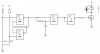
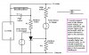
Hello. I am asking this question here as the relays I have bought for this purpose don't do what I want. First the load I am trying to switch is carrying milliamps. That is why I think I can do it with electronics. Control voltage is 12 volt dc. I need to have two 12vdc +pulse inputs in to control this switch. I need a N.C. contact at rest. Pulsed on one input it would open to a N.O. position & stay their until it was pulsed again throught the other input & it would then return to N.C. If possible I would like the N.C pulse to delay for 5 seconds before it opened. The return pulse to close would be instantanious. The application is on my car alarm. I am using the lock pulse to open the N.C. circuit & the unlock pulse to return the switch to N.C. position. I am trying to take a lock sense circuit out of the circuit while the alarm is on & reuturn it back to normal when the alarm is off. I hope this makes sense to some one. I can buuild the circuit but my electronics was 20 years ago & I am an electrician.  Thanks
Thanks