Continue to Site

Welcome to our site!

Electro Tech is an online community (with over 170,000 members) who enjoy talking about and building electronic circuits, projects and gadgets. To participate you need to register. Registration is free. Click here to register now.

  • Welcome to our site! Electro Tech is an online community (with over 170,000 members) who enjoy talking about and building electronic circuits, projects and gadgets. To participate you need to register. Registration is free. Click here to register now.

pulse needed from a perm voltage

Status
Not open for further replies.

planty

New Member
Hi,
I need a 12 pulse every time 12v comes on,
for a friends car im looking at,
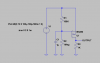
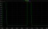
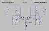
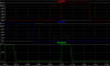
when you unlock the cars 12 volts stay on and when you lock the car the 12 volts swap over to the lock wire, now i need a pulse each time the power swaps over, i have looked into the 555 timer but i cant work out how to get a pulse, I am using a program "ciruit wizard"
any help would be great.
 
planty,

Attached is a circuit that I helped a student with, to detect the daily activity of 3mm blind cave fish. The input has been modified to detect positive going 12v levels...as in your lock system. I think this will do it.

Ken
 

Attachments

  • Change Detector.gif
    Change Detector.gif
    26 KB · Views: 162
Thanks for that, but thats a bit much i think, just a basic kit
when i recive 12volts i just need a pulse.
Then i can just make another one for the other lock...
 
Hi Planty,

Is this simple enough ?

on1aag.
 

Attachments

  • Pulse schematic.PNG
    Pulse schematic.PNG
    13.5 KB · Views: 167
  • Pulse.PNG
    Pulse.PNG
    13.7 KB · Views: 150
OK...a little less complicated. RA and CA can be paralleled with as many lock/unlock inputs (RB/CB, RC/CC....RX/CX) as needed. Whenever one lock/unlock changes there is a fixed width pulse out of the 555. Or, if you don't care about the output pulse width...there is one without the 555 monostable.

Ken
 

Attachments

  • Change Detector2.gif
    Change Detector2.gif
    16.2 KB · Views: 189
  • Change Detector3.gif
    Change Detector3.gif
    10.8 KB · Views: 238
KMoffett said:
OK...a little less complicated. RA and CA can be paralleled with as many lock/unlock inputs (RB/CB, RC/CC....RX/CX) as needed. Whenever one lock/unlock changes there is a fixed width pulse out of the 555. Or, if you don't care about the output pulse width...there is one without the 555 monostable.

Ken

That look easy ish, but what is that 2n3904 - Q1 thing?
 
on1agg,

Could you complete your schematic with two inputs, one from a 12v locK wire and one from a 12V unlock wire, as in planty's original description. Lock is always high or unlock is always high, and with positive output pulse as in your signal display for the "change over". I might be just missing something in your approach.

planty:
And not knowing what you are going to do with the 12v pulse...one more with even less.

Ken
 

Attachments

  • Change Detector4.gif
    Change Detector4.gif
    5.9 KB · Views: 153
Last edited:
KMoffett said:
OK...a little less complicated. RA and CA can be paralleled with as many lock/unlock inputs (RB/CB, RC/CC....RX/CX) as needed. Whenever one lock/unlock changes there is a fixed width pulse out of the 555. Or, if you don't care about the output pulse width...there is one without the 555 monostable.

Ken

just made this up and no power goes past the resistors or the capacitors
try the other one now
 
KMoffett said:
on1agg,

Could you complete your schematic with two inputs, one from a 12v locK wire and one from a 12V unlock wire, as in planty's original description. Lock is always high or unlock is always high, and with positive output pulse as in your signal display for the "change over". I might be just missing something in your approach.

planty:
And not knowing what you are going to do with the 12v pulse...one more with even less.

Ken

just made this one up also and the same thing, no power get past the resistors or the caps..
 
Hi Planty,

O.K. now it's stereo !

on1aag.
 

Attachments

  • Pulse schematic 2.PNG
    Pulse schematic 2.PNG
    15.9 KB · Views: 139
  • Pulse 2.PNG
    Pulse 2.PNG
    13.7 KB · Views: 132
KMoffett said:
OK...a little less complicated. RA and CA can be paralleled with as many lock/unlock inputs (RB/CB, RC/CC....RX/CX) as needed. Whenever one lock/unlock changes there is a fixed width pulse out of the 555. Or, if you don't care about the output pulse width...there is one without the 555 monostable.

Ken

well this one works now. it help if i put power to no.4, i think i need a bit longer time on the pulse. i will have a play,
 
on1aag said:
Hi Planty,

O.K. now it's stereo !

on1aag.

well tried this one, and instead of a pulse it puts out 7.3 volts all the time,
Back to square 1, unless i can get a longer pulse in that other one.
 
planty,

When you say you need a bit longer time on the pulse...what do you mean...?
It really simplifies things if you can tell all of us what you need...from the start. You never said what you where you were going to do with "a" pulse...just that you wanted one.

The devil is in the details.

Ken
 
planty said:
well tried this one, and instead of a pulse it puts out 7.3 volts all the time

I wouldn't bet any money on it ! :D

on1aag.
 

Attachments

  • AGF00014.JPG
    AGF00014.JPG
    219.9 KB · Views: 327
KMoffett said:
planty,

When you say you need a bit longer time on the pulse...what do you mean...?
It really simplifies things if you can tell all of us what you need...from the start. You never said what you where you were going to do with "a" pulse...just that you wanted one.

The devil is in the details.

Ken

right, I need to close the front electric windows for a ford escort, There is always power to the door motors, either when it is locked or unlock, like a flip flop,
With the vauxhall cars they are pulsed, and i have pcb's made up for this, when a pulse is recived from the deadlock the timer is activated for about 17 seconds and when the unlock pulse trips in it stop the timer, (safety feature)
But if you put the same circuit board to the ford car, it keeps triggering/reseting itself, so it keeps trying to close the windows.

or is there another kit that once you put constant 12v in then the timer will work for about 17 seconds and if it goes to unlock within that timed limit will stop.
 
Status
Not open for further replies.

Latest threads

New Articles From Microcontroller Tips

Back
Top