Electro Tech is an online community (with over 170,000 members) who enjoy talking about and building electronic circuits, projects and gadgets. To participate you need to register. Registration is free. Click here to register now.
Welcome to our site! Electro Tech is an online community (with over 170,000 members) who enjoy talking about and building electronic circuits, projects and gadgets. To participate you need to register. Registration is free. Click here to register now.
Then why not vary pin 5 for frequency, and use the dual diodes w/pins 2 & 6 for duty cycle? I've thought about trying that, but each time I think about it, I just don't think using pin 5 works very well. Course, I've been too lazy to try it.
Edit: The more I think about it, the more I think it should work, depending on how good the timer comparators are.
Generally speaking, classical pulse generators had very fast rise- and fall-times. The typical unit had adjustments for pulse frequency (or period), pulse width, rise time and fall time. Positive-going and negative-going outputs were available and the amplitudes on both were adjustable, on older units often going as high as ±80 or 90 volts peak. The units were always oscillators that drove one-shots and the oscillator on some models could be configured for single-pulse or triggered operation.
One of the characteristics of this oscillator/one-shot combination was that the operator was always accidentally setting the oscillator such that it's period was shorter than the pulse. Of course, the result was the the output pulse disappeared since the one-shot was being retriggered before it completed its previous pulse.
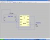
I used an N-channel MosFet instead of a P-channel type because of generally lower RDS(ON).
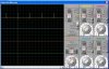
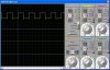
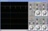
Here are the simulation results. (tried with 47nF and 22nF without change of properties, motor model used: 9V/6Ω, load/max torque 50%)
There is a voltage drop of approximately 400mV across the transistor not allowing full speed of the motor. You might use a switch to bypass the transistor for full rpm. (also shown in the schematic)
This site uses cookies to help personalise content, tailor your experience and to keep you logged in if you register.
By continuing to use this site, you are consenting to our use of cookies.