Continue to Site

Welcome to our site!

Electro Tech is an online community (with over 170,000 members) who enjoy talking about and building electronic circuits, projects and gadgets. To participate you need to register. Registration is free. Click here to register now.

  • Welcome to our site! Electro Tech is an online community (with over 170,000 members) who enjoy talking about and building electronic circuits, projects and gadgets. To participate you need to register. Registration is free. Click here to register now.

PT100 interface design

Status
Not open for further replies.

r.youden

New Member
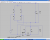
I am trying to design an interface for a PT100 temperature sensor (2-wire variant) with an output range of 0-1V. I currently have the sensor driven by a 1mA constant current source and a 100Ω resistor driven by an identical current source as a reference. These two signals are then connected to a 2 op amp differential amplifier constructed of one AD822 IC. In Proteous this circuit works fine but when it is constructed the op amps never fully go to ground, they sit at about 0.08V which corresponds to around 8degC, not great.

Now one solution I could think of would be to generate a negative supply of the op-amp so the voltage could swing around 0V but and negative supply generator would have to be cheap and relatively small.

I really am starting to chase my tail on this one. If anyone has any suggestions I would be very grateful.

Thanks,
 
I was under the impression that the AD822 is a rail to rail opamp, but it will only get as low as 0.08V, rather than 0V
 
Yeah, good point. If you look at the specsheet, the lowest guarentee VOL is 7mV, at 20uA output current. You might have an offset current or voltage problem. I would try modeling your circuit with the published offset specs and see what happens.

If you're using ideal opamp for your simulations, you can model offset behavior using external sources at the input pins. See Microelectronic Circuits by Sedra and Smith for an explaination, or else I can look it up for you later tonight.
 
Last edited:
Your requirement (that the output goes from 0 to 1V) is not possible if operating from a single supply with the - end connected to 0V. You can do it with a floating single supply (where the 0V is defined inside the circuit), or by using two supplies connected V+, 0V, V-.

Another way is to simply change your requirement to offset the voltage range so that it goes from say 0.1V to 1.1V, still a 1V delta.
 
Last edited:
What I've been looking at it the easiest way of making a negative supply for my circuit. If it was a 'money no object' solution I would throw a Traco in there, but I don't have that luxury. I have been looking for a solution that uses the spare opamp in my circuit and I found a solution that used an extra Zener but that didn't work when I simulated. Does anyone have an easy solution to generate a negative voltage?

Thanks.
 
If you can get to your power supply's transformer, you can generate a negative rail by reversing a doubler circuit.
 
In the attached circuit, a doubler is added to a typical power supply, AC transformer, full wave rectifier and filter. R2 models the load, and represents any circuit that operates on the positive voltage. The components C1, C2, D1 and D2 make a doubler for the generation of a low power negative rail. The negative rail is taken at the anode of D1. R1 represents a low power load for the negative voltage. This represents one way a typical power supply can be modified to generate a low power negative rail for full bipolar opamp operation.
 

Attachments

  • negative_generator.PNG
    negative_generator.PNG
    66.5 KB · Views: 838
Last edited:
Status
Not open for further replies.

New Articles From Microcontroller Tips

Back
Top