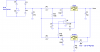
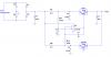
I haven't built and tested this, but the simulation works really well. The basic idea is to use one of the regulators as a master, and then use a diff amp to force the current through the slave regulator to be the same as that of the master. The op amp output forces the ADJ (or GND) pin on the slave to whatever voltage is required to make the currents equal.
If you use a slave with a nominally lower output voltage than the master, you can get away with a single supply. For example, the master could be a 7812, and the slave a 7805. They both wind up dissipating the same power, because the 7805 will have +7V on the GND pin.
If you use two identical regulators, e.g., 7812's, you will need a low-voltage, low-current negative supply for the op amp, because the slave might need to have the GND pin pulled negative by as much as a few hundreds of millivolts.
The op amp needs to have a common-mode range that includes the positive rail. I played around with other amplifiers, including a discrete PNP differential pair, but the op amp is the easier, and performs better.

")
")