Continue to Site

Welcome to our site!

Electro Tech is an online community (with over 170,000 members) who enjoy talking about and building electronic circuits, projects and gadgets. To participate you need to register. Registration is free. Click here to register now.

  • Welcome to our site! Electro Tech is an online community (with over 170,000 members) who enjoy talking about and building electronic circuits, projects and gadgets. To participate you need to register. Registration is free. Click here to register now.

Proportional control for Dagonfly helicopter

Status
Not open for further replies.

davegriff

New Member
Proportional control for Dragonfly helicopter

Hi guys,

This is my first post on the forum, and hope someone can help. I've been through the threads and haven't found a solution yet.

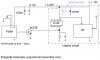
I have, amongst other r/c aircraft a Dragonfly 2 channel helicopter, really just a toy. Controls presently are simple up, down, hover, spin left and right, non-proportional. Although described as a 2 channel control, chips used are the tx/rx-2b 5 function job designed for toy cars. Data sheet is here:

datasheet4u.com/html/T/X/-/TX-2B_SilanSemiconductors.pdf.html

It occured to me that if one of the functions could be made proportional, it would leave 2 spare channels to control direction (currently not available).

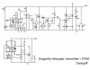
Early experiments are good. Replacing the original full speed on/off switch in the transmitter with a PWM circuit to control the main motor works well, the motor speed now being truly proportional, hopefully giving much better up/down/hover control. (so far without any changes to the receiver end)

However there's one snag so far with the circuit I've used. If any part of my body gets too close to the circuit (or the aerial), the motor spins up to full speed, dropping back to controlled speed if I move away again. I've tried various decoupling caps etc to no avail.

If anyone can help I'd be much obliged.

Davegriff
 

Attachments

  • circuit.jpg
    circuit.jpg
    28.5 KB · Views: 1,122
Last edited:
Hi Davegriff,

That's a very clever solution that harks back 50 years to when we used "galloping ghost" controls for model airplanes, namely a PWM modulated control at very low frequencies. The inherent control was either full on or off.

I am not familiar with that chip set per se; however, I notice that your PWM frequency of 35 Hz is very close to some of the control word lengths. For example, "turbo" is
30 mS (33 Hz) (i.e., 4x2mS + 22X1mS). Have you tried a much lower PWM frequency, such as 10Hz or lower. That shouldn't make too much difference to the motor driving a helicopter blade. It can't respond to any frequency very well.
Good luck. John
 
thanks John for response. Yeah well I am getting on a bit myself, but young at heart.

Good idea though. I actually started at about 200 hz, went up to a few khz and back down (all same effect). Wasn't sure whether motor would run too jerkily at 10hz but will try anyhow.

Davegriff
 
more.......

Just tried circuit with PWM running about 10hz.

Seemed to work ok at first - no speeding up but not getting full revs because battery in chopper was a bit low so tried with fresh battery.

This gave zero to full revs but speeding up effect returned! Could it be I'm overloading the tx (or rx?) somehow. Tx is on 27mhz, uses 5 transistors, but apart from that I haven't given much attention to it so far.

I'll work out the tx rf circuit and post it when I'm done as that might help.

Davegriff
 
I think the very cheap single transistor radio receiver (a super-regen) overloads when the transmitter is near.

A real radio receiver has a lot more than just a single transistor.
 
Suppose it could just about be the receiver at fault, and it doesn't show up normally because the signal's not usually pulsed.... but its surely more likely to do with added circuitry - that's why I asked the question initially. I've tried it again - full battery, 20ft between tx rx, aerial not extended - same result.

I have real tx's/rx's and could rebuild the chopper with one of these, or easier, go out and buy a £200 chopper to play with. but that wasn't the point of doing this. I just like tinkering, and pushing the limits of a £10 toy (albeit with real/imaginary receiver) appeals to me. I'd also like to learn something along the way.

Davegriff
 
I don't think the problem is in the super-regen receiver per se. That was all we had for years. I still suspect the problem is in the coding/decoding. Either the transmitter or receiver isn't handling it. When we had signle-channel, super-regen receivers and escapements, our pulse rates were manually generated and were very low, because the feedback loop was what the airplane did in flight. Albeit, helicopters are a lot more sensitive than our intermittantly guided free-flight models were, but for motor power, I think you can still go lower in frequency.

Now, why did the battery charge have an effect? Do you have effective capacitors and/or other noise suppression on your motor? It does seem odd, though, that the receiver can decode reliably the transmitter signal, but not simple on/off modulation.

As for low frequency PWN, obviously you can do it with discrete elements as you have shown. Last week, however, I bought a little signal generator on e-bay for about $120 USD that goes to fractional hertz, has adjustable duty cycle, and display of frequency and amplitude. I don't know if yout tinkering budget would include something like that, but I am very happy with it. The brand in the USA is Victor VC2002. Here's a link:
**broken link removed**

John
 
Last edited:
Cheap toys use simple super-regen receivers.
Ordinary half-decent model airplanes, helicopters, cars and boats have used good super-heterodyne receivers for years and they work very well.
 
Thanks for the link John - might get me one of those. Got several hobbies including computer programming and current pc coming up for renewal so should really look into replacing first as its used for business as well (but money not really an issue issue here) nice kit at good price though. So many things to do.

I'll work out tx circuit (this is for FUN and knowledge, audioguru) and post again. Got super het tx's and rx's lying around but like I said, could buy another heli but don't intend to yet.

Right now I need some sleep.

Thanks both for interest
Davegriff
 
The signal generator is not a kit, nor is it based on the old Maxim chip. It's made in China (of course) to ISO9001. The real manufacturer is not given, so I can't help you there. I have seen identical units on the Austrailan site for a similar price, if converted, and haven't checked the UK site. I got it because of the display and low-frequency range. It's max is 2 MHz, and the square wave looks pretty bad at the frequency. John
 
No offense taken. Right after I posted, I recalled the different use of the word, as in soldier's kit, mess kit, etc. I decided to leave it as was, because the price is so relatively low, one might think that it was a kit to be constructed and not a completed unit.

Any updates? With the PWN frequencies I am suggesting (e.g., 2 to 4 Hz), you could probably simulate them with your thumb or a mechanical switch, just to see if the problem still exists. John
 
Haven't tried lower frequency yet but here's the circuit + that of pwm.

I posted query first about six hours earlier, but when it didn't appear in the forum and could find no record of it I posted again. Its now appeared so is showing twice! Know how I can get rid of the other?

............................

Had gone to bed when I had an idea. The original circuit has a pull up resistor + diode linking the left/right and boost control pins (presumably to give full throttle during spins). Tried a pull up res on the output transistor of the pwm and its solved the problem! Great - now all I need to do is tidy up the tx and somehow use the two spare channels for direction (work on rx I think).

Guess that will teach me not to mess with a circuit till I know what it does.

Many thanks for your help John, will let you know how I get on. Davegriff
 

Attachments

  • dragonfly tx.jpg
    dragonfly tx.jpg
    30.1 KB · Views: 1,968
Last edited:
I've looked at the two schematics you have posted, and nothing jumps right out at me as being wrong. But, I am more of a "try it" type person with a breadboard, rather than one who etches a PCB and solders in components based on my knowledge of design. One question though: Why do you power the PWM add-on from "B" rather than from Vdd? Could the added voltage drop across R9 during the PWM "on" cycle be enough to upset the transmitter?

The result that still bothers me is why the system seemed to work when the receiver batteries were low, but not when fully charged. John
 
Sorry. Edited post with schematic but must have been after you looked at it.
Solved the problem with a pullup res. Take a look and at following post to that.

A-A just to be sure not to over voltage tx-2b. Now take a look at new jpg. Removed a couple components and somehow blew the zener open circuit and pumped 7+ volts into tx-2b. can't find solder shorts etc, so may be coincidence. I've got another tx-2b if its blown but no zener low enough and can't remember how to wire transistor as zener. Is it base joined to emitter and z across collector emitter (npn). Live out in the sticks - have to buy on internet, postage etc for small orders here are ridiculous, so may have to wait a while.

Worked a treat though. late here so logging out now.
Dave

thought - might find a 7805 some to rig something.
 

Attachments

  • dragonfly tx new.jpg
    dragonfly tx new.jpg
    32.4 KB · Views: 437
The base-emitter diode of a silicon transistor has a max reverse voltage rating of only 5V because it has avalanche breakdown (like a zener diode) at about 7V. If you include the collector-base diode in series then the voltage is about 7.7V.
 
Thanks for info Audioguru - you can do positive comments :). I know these things are cheap, but not everyone can afford expensive planes and may want to copy what I've done.

Realise now though I didn't need to disconnect transistor/diode anyway! Will replace zener and put tx-2b in socket.

Dave
 
Model airplane clubs have a group of guys who fly tiny lightweight RC planes in school gyms. Many use the simple radio control electronics that come in $10.00 RC mini cars.
 
Agreed.

Perhaps I'm wrong but I didn't think they used proportional motor control - its not available directly through the tx-2b. The tx-2C has a sort of pwm control on one pin but I think it just gives 50% cycle. A lot of sellers of these toys claim proportional control for stuff with only 2 or 3 set speeds.

David
 
Status
Not open for further replies.

Latest threads

Back
Top