Electro Tech is an online community (with over 170,000 members) who enjoy talking about and building electronic circuits, projects and gadgets. To participate you need to register. Registration is free. Click here to register now.
Welcome to our site! Electro Tech is an online community (with over 170,000 members) who enjoy talking about and building electronic circuits, projects and gadgets. To participate you need to register. Registration is free. Click here to register now.
Hi everyone,i want to make a programmable current source/sink (source or sink depending on a digital signal) but i am a beginner and i don't have a clue...It has to provide 0-10uA,10 bits resolution,can anyone help???
Thank you!!!But,as i told you i don't know much,so could you explain the circuit a little bit?Also,do you have specific parts (op. amps etch.) to suggest for the implementation because i don't have much experience.
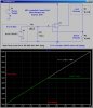
The OpAmp has feedback around it such that it makes the voltage across R2 (the 10K shunt resistor) follow the voltage at the non-inverting input. That determines the current through R2, which must be the same as the current through the load resistor (because the gate current of a FET is ~0).
The voltage at the non-inverting input of the OpAmp is divided down from the output of an Digital to Analog Converter (DAC, not ADC like in the schematic), e.g. a DAC6571. There are hundreds of similar DACs from various IC makers available.
The OpAmp could be a TLC2272 (dip package), or any of hundreds of similar ones available from various IC makers.
1. Use a p-type mosfet instead
2. Swap op-amp inputs so it is positive feedback
3. Place the power supply on the source side of the mosfet
4. Place the sense resistor on the drain side, after the load, and before ground
Hee hee, i just had to ask because normally MOSFETs are employed to provide fairly high currents and after all the little op amp can surely handle 10ua all by itself can it not? <chuckle>
Hee hee, i just had to ask because normally MOSFETs are employed to provide fairly high currents and after all the little op amp can surely handle 10ua all by itself can it not? <chuckle>
What is so funny??? If you notice, the NFET I specified is tiny; I used it as a voltage-controlled current-source. Do you have a circuit that makes a current-source for a ground/VDD referenced load using just an opamp and some resistors? Obviously, you can put the load in the feedback path, but that forces you to have a "floating" load.
What is so funny??? If you notice, the NFET I specified is tiny; I used it as a voltage-controlled current-source. Do you have a circuit that makes a current-source for a ground/VDD referenced load using just an opamp and some resistors? Obviously, you can put the load in the feedback path, but that forces you to have a "floating" load.
What is so funny??? If you notice, the NFET I specified is tiny; I used it as a voltage-controlled current-source. Do you have a circuit that makes a current-source for a ground/VDD referenced load using just an opamp and some resistors? Obviously, you can put the load in the feedback path, but that forces you to have a "floating" load.
Sorry, didnt mean to come off like i was mocking the circuit or something. When i looked at it i just couldnt help but wonder what an output transistor would be needed for when the output current requirement is a mere 10ua (ten microamps). It's not that bad of any idea though so dont get me wrong here.
Since the op amp can easily put out 10ua i believe we can find a circuit that will do this using the capability of the op amp alone without requiring an output drive stage, but i'd like to see what CafeLogic has to offer before i post if you dont mind waiting just a bit.
Op amps are such versatile devices and even though i've worked with them both theoretically and on the bench for years and years they never cease to amaze me.
CafeLogic:
Yes as Mike pointed out that circuit is not ground referenced. It has to be ground referenced to keep the OP happy
LATER: oh ok i see you want to use two op amps, right?
If someone had asked me to do the same thing, I also would have used a pass transistor and not thought twice and I didn't think twice about your circuit. It's not like the circuit wasn't good, it's just funny to me how my habits block my own innovation. Here is an abbreviated schematic as requested.
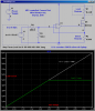
I had a hunch that this could be done using one single op amp though so that brought about the following circuit.
It should be noted though that the output equation contains the load resistance (R5) in at least one place and to cancel that resistance out requires the products as shown on the schematic to be the same. Also as noted, if all the resistances are made equal this is easily met. To find out the effects of a mismatch of these two products we could do a few simulations. It may require 1 percent tolerance resistors but again we'd have to do a quick study to find out for sure. I have a feeling it would mostly affect the gain.
Vin in the schematic is the assumed 5v DAC but the resistor values can be adjusted for other levels.
This site uses cookies to help personalise content, tailor your experience and to keep you logged in if you register.
By continuing to use this site, you are consenting to our use of cookies.

 ... This is for sink,right? What do i have to do for source?