Continue to Site

Welcome to our site!

Electro Tech is an online community (with over 170,000 members) who enjoy talking about and building electronic circuits, projects and gadgets. To participate you need to register. Registration is free. Click here to register now.

  • Welcome to our site! Electro Tech is an online community (with over 170,000 members) who enjoy talking about and building electronic circuits, projects and gadgets. To participate you need to register. Registration is free. Click here to register now.

Programmable 555 timer draining high current

Status
Not open for further replies.

pavjayt

Member
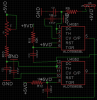
I have a circuit a programmable timer based on 555 timer as shown in the attached picture. But this circuit drains a lot of current from my 5V supply depending on the value of P1 and the consumption varies as high as 200mA sometimes. Is there something wrong with this circuit or is it common? I even had P1 go bad on one of the boards. The input to this is a TTL signal. I had a 1K pot connected to X6.

thanks
 

Attachments

  • ALD7556.png
    ALD7556.png
    245.1 KB · Views: 182
  • ALD7556_SCH.png
    ALD7556_SCH.png
    82 KB · Views: 190
The timing resistors R9 and R10, 10 ohms are too low.
Change them to a few kilo-ohms and then change the corresponding capacitors to keep the timing right.
 
At their minimum settings the 1kΩ pots only have 10Ω in series with the 5V supply. That can draw several hundred mA peak current through the pots when the 555 discharges the capacitor. You should have at least 100Ω in series with the pots. If you need a shorter period from the 555s then make C21 and C22 smaller.

That high current could also be what caused the pot failure. The maximum safe continuous current through a pot is √(P/R) where P is the pot power rating and R is the pot resistance value.
 
Thank you for both of your replies. I use this circuit mainly to adjust the phase of incoming TTL signal, I actually don't need to use P1 as I don't need to do any duty cycle adjustments. In this case, what would be the ideal constant values for C22, R10 and P1 (will be replaced by a resistor) and if I change R9 to 100, what would be the ideal value for C21?
 
The 7556 IC is not an ordinary 555 timer. It is a dual Cmos 555 timer.
I think the 10 ohms value timing resistors has destroyed the IC and would also destroy an ordinary 555 timer IC.
 
Status
Not open for further replies.

Latest threads

New Articles From Microcontroller Tips

Back
Top