Alex_bam
New Member
Hello,
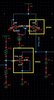
I have designed an LPF demodulator. In a normal situation it's working fine, however when I carried out the Process corner simulation, the threshold voltage of MOSFET changes which is obvious, due to which MOSFET's operation region changes, ultimately change the output.
My question is :
1-How to compensate for the process corner variation?
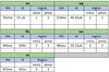
Note: I have attached the simulation circuit along with the table which illustrates variations in : Threshold voltage, Id, and region during different process corners.
Region: 0 "cutoff"; 1 "linear"; 2 "saturation"; 3 "subth"
Process Corners:
tm = Normal situation
wp = worst-case power
ws = worst-case speed
wo = worst case one
wz = worst-case zero
Thanks.
I have designed an LPF demodulator. In a normal situation it's working fine, however when I carried out the Process corner simulation, the threshold voltage of MOSFET changes which is obvious, due to which MOSFET's operation region changes, ultimately change the output.
My question is :
1-How to compensate for the process corner variation?
Note: I have attached the simulation circuit along with the table which illustrates variations in : Threshold voltage, Id, and region during different process corners.
Region: 0 "cutoff"; 1 "linear"; 2 "saturation"; 3 "subth"
Process Corners:
tm = Normal situation
wp = worst-case power
ws = worst-case speed
wo = worst case one
wz = worst-case zero
Thanks.