Continue to Site

Welcome to our site!

Electro Tech is an online community (with over 170,000 members) who enjoy talking about and building electronic circuits, projects and gadgets. To participate you need to register. Registration is free. Click here to register now.

  • Welcome to our site! Electro Tech is an online community (with over 170,000 members) who enjoy talking about and building electronic circuits, projects and gadgets. To participate you need to register. Registration is free. Click here to register now.

Problems with PIC16F877A connected with LCD module...

Status
Not open for further replies.

si2030

Member
Hi All,

I have connected the above together and have used as a basis Nigel's LCD program. Yes it works however its not working well... if I can say that.

The problem is, it takes a really long time to start up seconds. However it displays the first letter almost instantly.... I then wait three or four even five seconds before the other letters show... When the other letters display it roles through the letters. If I touch the metal surround of the LCD it goes alot quicker almost instantly starting.

If I turn the encoder (also on the board) it restarts... If I bring my hand close without touching it, it restarts by itself.

It has also corrupted the hex file within the PIC.. I know this as I read it back and it looks line some of the hex is missing or its all gone... once I reloaded it worked as above...

I have checked all the connections and they appear to be behaving correctly.. I tried adding a cable to separate the LCD from the board but it still operaties as above...

I am using a zif socket to manage the PIC.

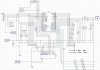
I have included the schematic and the working asm file as it could be both

Wondering if you might have some suggestions for this... could it be a dry joint... or is it a function of a double sided board not earthed correctly... I did check the earth and seems OK..

Kind Regards

Simon
 

Attachments

  • LCD 1-1..asm
    11.3 KB · Views: 168
  • Schematic..jpg
    Schematic..jpg
    357.9 KB · Views: 563
The most common reason for this sort of problem is the MCLR pin not being pulled up to 5V. I see it is in the schematic but can you verify that the pin actually is on the board?

You should also use a 10K resistor on MCLR. Every time you push the reset switch it shorts out your power supply...
 
Last edited:
The most common reason for this sort of problem is the MCLR pin not being pulled up to 5V. I see it is in the schematic but can you verify that the pin actually is on the board?

You should also use a 10K resistor on MCLR. Every time you push the reset switch it shorts out your power supply...

OK so I placed a 10k reistor from MCLR to ground and it seems to work much better... I will splice that into the system and see if it works with it sodered in...

Thanks.

Simon
 
OK so I placed a 10k reistor from MCLR to ground and it seems to work much better... I will splice that into the system and see if it works with it sodered in...

Thanks.

Simon


On your schematic you have MCLR tied directly to 5V, which is where it should be...

BUT

you need to remove this connection and replace it with a resistor. No need to have a resistor to ground.

Also check your connection between the newly placed resistor and 5V.
 

Attachments

  • Untitled..gif
    Untitled..gif
    83.1 KB · Views: 329
Last edited:
hi,
There are problems with your program.
In the CONFIG its coming up as LVP_ON

I have corrected the CONFIG statement.

The Call Delay50 in the BUSY check subr is slowing down the display of each character.

Try this asm file, it now works OK in Oshonsoft Sim.

EDIT:
I like the way you have taken the trouble to comment the program listing and the PIC pin image.:)
It makes set up and debugging so much easier for someone trying to help you.
 

Attachments

  • LCD 1-2..asm
    10.9 KB · Views: 118
Last edited:
To both of you thankyou... I am a strong believer in good documentation and hopefully simple well thoughout code... it gives people like you half a chance to help.. will let you know tomorrow... simon
 
The most common reason for this sort of problem is the MCLR pin not being pulled up to 5V. I see it is in the schematic but can you verify that the pin actually is on the board?

You should also use a 10K resistor on MCLR. Every time you push the reset switch it shorts out your power supply...

In my modest experience, the most common reason for this type of behavior is LVP not being turned off.
 
Hi Eric, Mike,

Yes it now works perfectly. Thankyou. Having the configuration word with LVP (low voltage in circuit programming - I have just found out) turned off required the device to require 13volts to reprogram rather than MCLR at 5volts and RB3 at five volts... its stable and working now thankyou.

Simon
 
In my modest experience, the most common reason for this type of behavior is LVP not being turned off.

Cool, I've learnt something new. I've never come across that problem because I always have LVP turned off.


To the OP: have you put that resistor in? Otherwise you are shorting out the power supply when you push reset.
 
Last edited:
Status
Not open for further replies.

Latest threads

New Articles From Microcontroller Tips

Back
Top