IlordrossI
New Member
I am having a couple of problems with my clock circuit can any one help?
I am have to using the following IC chips: (kind of fried the last batch)
7493 Binary counter
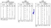
7447 BCD to 7-Segment Decoder/Driver
7 Segment Displays
Problem:
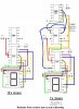
1.) I have created this section of a 12-hour clock. The ONEs HOUR section counts 0-12 I only want it to count 1-12. What do I have to do to alter this drawing so that it will count 1-12?
( The funny c, backwards c, and the top of a four shapes)
2.) The count sequences counts 0 1 2 3 4 5 6 7 8 9 [ ] u . After making the sequence not count the zero I want to get the count to count 1 2 3 4 5 6 7 8 9 0 1 2 instead of the shape how can I do this?
3.) Next I have to run the ONEs HOUR to the TENs HOUR and connect them so that the LED turns on and only shows 1 when the other counter counts 0 1 2 (which means ten, eleven, & twelve) after the 1 2 3 4 5 6 7 8 9 count. What can I do?
Please help, if you can with any of these problems I am having.
Thanks.
I am have to using the following IC chips: (kind of fried the last batch)
7493 Binary counter
7447 BCD to 7-Segment Decoder/Driver
7 Segment Displays
Problem:
1.) I have created this section of a 12-hour clock. The ONEs HOUR section counts 0-12 I only want it to count 1-12. What do I have to do to alter this drawing so that it will count 1-12?
( The funny c, backwards c, and the top of a four shapes)
2.) The count sequences counts 0 1 2 3 4 5 6 7 8 9 [ ] u . After making the sequence not count the zero I want to get the count to count 1 2 3 4 5 6 7 8 9 0 1 2 instead of the shape how can I do this?
3.) Next I have to run the ONEs HOUR to the TENs HOUR and connect them so that the LED turns on and only shows 1 when the other counter counts 0 1 2 (which means ten, eleven, & twelve) after the 1 2 3 4 5 6 7 8 9 count. What can I do?
Please help, if you can with any of these problems I am having.
Thanks.
")