Hi all,
I am new to the world of PICs (love em!). I got my first 16F84 and made a programmer for it last month. Worked great so I ordered 5 more. This time they are the 16F84A-20/P model.
Of the 5, I am only able to program 2 of them. The other 3 are coming up with verify errors. Is it common to receive bad chips (3 out of 5 no less)? Or could there be something I'm doing wrong?
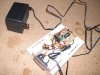
I'm using the Winpic Programmer and a home-built JDM (Serial) type of programmer. As I say, I can succesfully burn 2 of them, so I'm sure there's no problem with the programmer or software.
Thanks for any ideas you may be able to offer.
Daz
I am new to the world of PICs (love em!). I got my first 16F84 and made a programmer for it last month. Worked great so I ordered 5 more. This time they are the 16F84A-20/P model.
Of the 5, I am only able to program 2 of them. The other 3 are coming up with verify errors. Is it common to receive bad chips (3 out of 5 no less)? Or could there be something I'm doing wrong?
I'm using the Winpic Programmer and a home-built JDM (Serial) type of programmer. As I say, I can succesfully burn 2 of them, so I'm sure there's no problem with the programmer or software.
Thanks for any ideas you may be able to offer.
Daz
")