Continue to Site

Welcome to our site!

Electro Tech is an online community (with over 170,000 members) who enjoy talking about and building electronic circuits, projects and gadgets. To participate you need to register. Registration is free. Click here to register now.

  • Welcome to our site! Electro Tech is an online community (with over 170,000 members) who enjoy talking about and building electronic circuits, projects and gadgets. To participate you need to register. Registration is free. Click here to register now.

Problem with ULN2003

Status
Not open for further replies.

Aidis

New Member
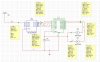
Can anyone help me build a schematic for a ULN2003 to drive a DC motor (Non-Stepper)? I know i have to connect pin 9 to Pwr (12v) and 8 to Grnd , and then lets say i have a computer output amped to 5v in the inputs of the ULN (With two states , power and no power) , how would i set up the motor on the outputs ..?
 
You would normally connect the motor between one of the output terminals(10-16) and the 12V + lead. Since you have pin 9 connected to +12 you could connect the motor leads between pin 9 and the output pin.
When a + 5 volt signal is on the associated input pin the motor will run.
Keep in mind the ULN2003 is only capable of sinking 500mA, so the motor must use less than that current when fully loaded.
If you need more current, you can easily use a darlington NPN and drive the transistor from a 5V input.
 
Scheme

Am i doing something wrong? Would it work like this..? (MultiSim)
 

Attachments

  • scheme_188.jpg
    scheme_188.jpg
    128.1 KB · Views: 1,814
I would assume that U3 has +5V on pin 20 and pin 10 is connected to ground, and that the 5 volt supply common is to ground. Then motor S1 should operate.
 
Do you have the Datasheet?
 

Attachments

  • uln2003a.pdf
    62.8 KB · Views: 626
Status
Not open for further replies.

Latest threads

Back
Top