Continue to Site

Welcome to our site!

Electro Tech is an online community (with over 170,000 members) who enjoy talking about and building electronic circuits, projects and gadgets. To participate you need to register. Registration is free. Click here to register now.

  • Welcome to our site! Electro Tech is an online community (with over 170,000 members) who enjoy talking about and building electronic circuits, projects and gadgets. To participate you need to register. Registration is free. Click here to register now.

problem with this cirucuit need help

Status
Not open for further replies.

jace33

New Member
ok guys need some help with this electronic project i have build three times and still no luck.

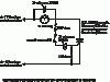
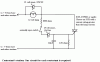
ok i have built three contestant stations etc.

but when i hook them all up contestant station is the only one that will light up and block the other two contestant stations out.

for eg if i push the second contestent station their light goes on but if you also push the third station contestant the second contestant station light goes out and the third station goes on visa versa

where station one contestnat light etc.. is the only one that lights up and blocks everyone else out.

please if anyone can help

thanks
 

Attachments

  • d.gif
    d.gif
    16.5 KB · Views: 144
  • dioid.gif
    dioid.gif
    11.8 KB · Views: 130
How about normally closed relays that would cut the power to the other signal buttons?
 
Several possible problems come to mind.

Ensure that the lamps at the main station and contestant stations are identical, this is important for the corrct operation of this circuit.

Are all the zener diodes the correct way round? Particularly the 15v zener.

Is your power supply 24v? If it is a bit low the circuit should work ok, but if it is high (26 or 27v) then you will get problems.

Does the problem only occur when the buzzer is sounding?
I can see a potential problem during the time the buzzer relay is energised, for a short time there will be enough voltage at the contestant stations for them to latch on when their button is pressed.

JimB
 
diode diagrame for circuit

ok in this circuit the diodes are marked like so where the straight line is or so called straght line where it meets the triangle is that where the striped side of the diode goes.?

ok and what i have done for the scr 2n5061 i have pin number 1 as the anode which goes to the light diode and resistor area and pin number 2 on the scr is the gate which goes to the switch and pin number 3 which is the cathode which goes to the resistor and followed on to the neg side of the input.
 

Attachments

  • d1.gif
    d1.gif
    1.2 KB · Views: 148
jace33 said:
ok in this circuit the diodes are marked like so where the straight line is or so called straght line where it meets the triangle is that where the striped side of the diode goes.?

ok and what i have done for the scr 2n5061 i have pin number 1 as the anode which goes to the light diode and resistor area and pin number 2 on the scr is the gate which goes to the switch and pin number 3 which is the cathode which goes to the resistor and followed on to the neg side of the input.

That's a zener diode, not a normal diode.
 
ok

i know that was just checking in the cirucuit diagram that is what the diode symbol is was just checking that the zenner diode where the strip is on it it has to be where the straight so called line meets the triangle is that right
 
jace33 said:
i know that was just checking in the cirucuit diagram that is what the diode symbol is was just checking that the zenner diode where the strip is on it it has to be where the straight so called line meets the triangle is that right

Yes it is.
 
ok thinking

ok am now thinking is the scr best to use a sensitive gate or a non sensitive gate as the scr 2n5061 in the circut is stated as a sensitive gate scr
 
Your problem may be due to the capacitance of the 15V zeners. Try adding a 10nF (0.01uF) capacitor in parallel with each 220 ohm resistor.
 
Jace33, in response to your PM, here is a schematic with the added cap. Do this on each station.
 

Attachments

  • station.gif
    station.gif
    12.5 KB · Views: 117
Good idea, this will also protect against false triggering cause by noise pickup.
 
Status
Not open for further replies.

New Articles From Microcontroller Tips

Back
Top