alisarhangpour
New Member
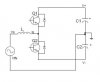
This image shows the power arrangement of a Power Factor Correction circuit. The dc bus voltage has to be divided, so when VIN is +, Q2 makes a boost circuit with Li & C1 and the revrse diode of Q1. And when VIN is -, vice versa.
It seems to have a problem: when VIN is +, and Q2 is being switched on, the inductor current will be conducted through C2 and so the voltage accross C2 will be decreased, which is undesirable. But this circuits works and Texas Instruments has admitted it in one of its technical data documents. How this problem is solved?
It seems to have a problem: when VIN is +, and Q2 is being switched on, the inductor current will be conducted through C2 and so the voltage accross C2 will be decreased, which is undesirable. But this circuits works and Texas Instruments has admitted it in one of its technical data documents. How this problem is solved?