Continue to Site

Welcome to our site!

Electro Tech is an online community (with over 170,000 members) who enjoy talking about and building electronic circuits, projects and gadgets. To participate you need to register. Registration is free. Click here to register now.

  • Welcome to our site! Electro Tech is an online community (with over 170,000 members) who enjoy talking about and building electronic circuits, projects and gadgets. To participate you need to register. Registration is free. Click here to register now.

problem with oscilator

Status
Not open for further replies.

will7

New Member
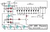
the oscilator in question is a sine/square wave generator catNo K7338 that I perchest from dicksmith electronics it uses a twisted ring counter set up to tern a square wave into a steped square wave and a butterworth low-pass filter(MF4CH-50 IC) to smooth out this signal into a fairly nice sine wave now this is where the problem occours I can find a sine wave at the out put of the MF4CH-50 but the signal just seems to end after a RC circut just after this IC I have cheched the solder joints a thousand times and cant seem to see any probs there? please help. and thanks for reeding this post.
 
Hi Will,
My very low distortion oscillator uses a CD4018 making a stepped sine wave and an LMF40-100 as its switched-cap 4th order butterworth filter.

Since yours doesn't pass its output thru the RC filter that removes the small amount of the switched-cap's clock, then the R must be open or have its value too high, or the C is shorted or has its value much too high.
Please post its schematic with parts values.
 
this could prove a bit of a problem as I dont have a scaner or a very good prog for writing up scematics :( this may take some time.
 
Microsoft "Paint" makes straight lines. I use it to draw schematics, like this one:
 

Attachments

  • 3v_chaser_schematic.jpg
    3v_chaser_schematic.jpg
    73.1 KB · Views: 608
I have finished the schematic but can not post it for some reason would not have a clue why
 
I think that it is the file type and size Ive saved it as .bmp file is about 10.6Kb big what would you recomend as I am a bit of a computer dumby.and how would I do this with only word pad and paint I also have windows media player but it is an old version
 
Open the BMP in Paint, select File at the top left, click on Save As and select GIF. Then post the GIF here.
If your Paint program is old and doesn't have GIF then save it as a JPG and post it here.
 
have sucess sorry it took so long I had to download another prog, there is one other question the op-amp before the output of the sine wave doesent have +5V at pin 7 but some how has it at pin 6 any clue?
 

Attachments

  • wave_generator.gif
    wave_generator.gif
    116.9 KB · Views: 579
From your scope readings there are only two possible causes:

1) The 3.3K is O/C

2) You have a S/C from the top of the 25K pot to ground.

This assumes the scope results apply where ever you set the pot!. Otherwise it could be a S/C after the pot (if it only disappears with the pot at maximum).
 
Your circuit is very similar to mine except mine uses a single 4018 to replace all your 4013's.
Yeah, the output of a TL071 is at pin6.
 
Thanks heaps for your replys guys I think I may need a little more help though with testing for the porblems that have been listed.
_____________________________________

I will keep trying though thanks heaps again.
 
Status
Not open for further replies.

New Articles From Microcontroller Tips

Back
Top