Continue to Site

Welcome to our site!

Electro Tech is an online community (with over 170,000 members) who enjoy talking about and building electronic circuits, projects and gadgets. To participate you need to register. Registration is free. Click here to register now.

  • Welcome to our site! Electro Tech is an online community (with over 170,000 members) who enjoy talking about and building electronic circuits, projects and gadgets. To participate you need to register. Registration is free. Click here to register now.

Problem with my Project: Motorised volume control

Status
Not open for further replies.

zenigame211

New Member
Hi there, I have been assigned to this new project recently and I am completely lost. I know little about PIC; therefore I hope some people can help me out.

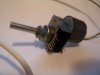
The aim of my project is :To be able to drive a potentiometer over a specified range of attenuation ratio using a stepper motor

• Input: Up/down momentary action pushbuttons to control movement of the potentiometer. Also a sensor must be provided to detect the ‘home’ position of the potentiometer.
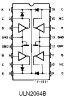
• Output: Hybrid 200-step stepper motor whose coil phasing must be controlled by the PIC.

I am researched little on the stepper motor and some notes on the PIC16F873. I think I will divide the project timeline into 2 sections. One on Software and the other on Hardware. I have 10 weeks to do this project. Hopefully there is enough time. Other than that Im not sure where to go.

Sorry, I am a total newbie in this and I do need some guidelines/help on this project. Please give me some ideas.

Thanks a lot!
 
zenigame211 said:
Any suggestions people?!?
the stepper motor is rotated by giving a sequence of pulses in it's input , which can be generated using a PIC, to reverse the rotation , reverse the sequence . giving the seq i/p one by one will step the motor . a micro switch like thing can be used to sense the home location.
 
Thather than thurning an pot whith a motor it would be a much better solution to get an digital pot IC.These ICs conect in insted of a pot and can comunictae whith an MCU over varius comunication protocols or by an simple up and down input that can be wired to a switch.
 
Someone Electro said:
Thather than thurning an pot whith a motor it would be a much better solution to get an digital pot IC.These ICs conect in insted of a pot and can comunictae whith an MCU over varius comunication protocols or by an simple up and down input that can be wired to a switch.
probably that is not his req.. may be a demo for a closed loop system with micro.
 
Can anyone still help me!?? I am still very lost. I cannot get the hardware design going. I have no idea where to go... I've searched for books and internet sites and still cant put myself on the right track.

Thanks
 
What does it mean by Up/down mometary action push buttons?

I know a buffer needs to be used to control the current. But can anyone tell me exactly the theory of a buffer? and how can it be used when apply to my project?

cheers,!
 
OK, I think you should at least provide a block diagram. If you don't have that, at least in your mind, you may not be cut out for this field. Speaking of field, what are you studying, or what career are you pursuing?
 
an easier way is to make or get a hold of a DAC.
Add a digital up/down counter to the inputs of the DAC and you can use the up and down functions of the counter to change the output resistance.
 
got this from electronic goldmine its a 20k ohms pot ,worm gear driven.
 

Attachments

  • motorizepot.jpg
    motorizepot.jpg
    48.2 KB · Views: 650
I am only in yr 1 Electronic and Electrical Engineering. I am not good in Micro controllers, therefore I am very worried about this project. It seems like I have no idea where to start off or am I actually on the right path.
 
I think I need to use an Astrosyn MY5002 mini hybrid stepper motor. I know the stepper motor require large currents if the load needs large torques.
I heard from my mates that I need a transistor array?? sth like that to drive the volume control... I don't understand why and what can I do with this though.

**broken link removed**
 
You're in your first EE year? Have you taken some electronics classes?
Well, like I said, you should start with a block diagram. Against my better judgment, I've drawn one for you. Once you have one, you can start identifying the pieces.
I showed the motor, the cam, and the pot all on one shaft. Obviously, they could just as well be connected by gears or belts.
If you have to control coil phasing with the PIC, you will need a simpler driver than one that takes step and direction as its inputs.
BTW, I don't really know much about steppers or PICs - just what I've gleaned from the Internet. That and 40+ years of stuff accumulated by osmosis. :D
I guess what I'm saying is, don't expect me (or anyone else) to design this for you. I have difficulty believing you would be assigned a project for which you have zero training.
 

Attachments

  • pot_controller.gif
    pot_controller.gif
    6.2 KB · Views: 762
Hi there, Thanks for your reply. I am not relying on anyone on this project. I just want someone to start me off so I know I am on the right path. I have done some micros in semester one and some basic analogue and digital electronics before. Hopefully I am alright.

As you said, the motor is connected together with the cam and pot in one shaft. I don't really understand that. Can you explain it more in depth. Thanks!
 
zenigame211 said:
Hi there, Thanks for your reply. I am not relying on anyone on this project. I just want someone to start me off so I know I am on the right path. I have done some micros in semester one and some basic analogue and digital electronics before. Hopefully I am alright.

As you said, the motor is connected together with the cam and pot in one shaft. I don't really understand that. Can you explain it more in depth. Thanks!
Why don't you explain how you propose to connect the motor to the pot, and how you plan to locate the home position? Then we can give you some feedback on your ideas.
 
hi there, I have been doing fine with my stepper motor so far. I am now a bit stuck at connecting from the PIC16f873 to the drive (ULN2064) and to the motor. I don't really get what the letters along the side of the pin stand for. I know there are 6 wires from the motor?.. and 4 of them goes to the driver and 2 goes to Vcc, but I dont have a lot of clues hows the pin allocation like.
 

Attachments

  • driver_214.jpg
    driver_214.jpg
    14.3 KB · Views: 363
Do you mean you don't know how to connect the motor, or the driver? Here is a datasheet for the **broken link removed** motor, if that's the one you're using.
 
I think there is a simple answer.

Why not make a DAC, and connect the output to the input of an H-bridge circuit and connect it's output to the motor?

If you do a search on google for H-bridge circuit, and you do a search for R/2R ladder, you could end up with results.

Now connect the digital input of the dac to the low-bit outputs of a counter IC of your choice.

Once you have that, adjusting the motor speed is as simple as triggering the clock pin of the counter.
 
mstechca said:
I think there is a simple answer.

Why not make a DAC, and connect the output to the input of an H-bridge circuit and connect it's output to the motor?

If you do a search on google for H-bridge circuit, and you do a search for R/2R ladder, you could end up with results.

Now connect the digital input of the dac to the low-bit outputs of a counter IC of your choice.

Once you have that, adjusting the motor speed is as simple as triggering the clock pin of the counter.

Try reading the thread! - your answer is completely wrong, in EVERY respect!.
 
Status
Not open for further replies.

New Articles From Microcontroller Tips

Back
Top