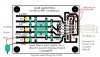
i am currently a student who is working on the h-bridge with L298 ic. This h-bridge is going to run 2 dc gear motor with 12v and 1.1A. I followed the circuit diagram from this website below.
**broken link removed**
However,this website didnt tell me what is the code for the diode. My friend recomment me to use either IN4001 or FR202. Which 1 will be suitable.
Is there anything i need to modify on this circuit diagram that i found?
**broken link removed**
However,this website didnt tell me what is the code for the diode. My friend recomment me to use either IN4001 or FR202. Which 1 will be suitable.
Is there anything i need to modify on this circuit diagram that i found?