lukas.ballo
New Member
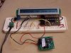
I tried to interface an LCD module (WD-C2401P-1GNN) with PIC16F886 (PICAXE 28X1) microcontroller however even after I send the ON command and apply 8-bit data to its 24 positions, nothing shows up. The display is driven by HD66717 which is one of those less common chips. Data sheet for this display is really poor and the information I found on-line did not help to solve the my problem.
Picture of the display:
**broken link removed**
Thank you very much for any ideas!!!
Connections:
[FONT="]1. GND -------------------------- (-)
2. VCC -------------------------- (+5V)
[FONT="]3. RESET ----------------------- (c0)[/FONT]
[/FONT] [FONT="]4. REGISTER SELECT ------ (c1)
[/FONT] [FONT="]5. READ/WRITE SEL ------- (c2)
[/FONT] [FONT="]6. ENABLE -------------------- (c3)
[/FONT] [FONT="]7. DATA BIT 0 --------------- (0)
[/FONT] [FONT="] ...
[/FONT] [FONT="]14.DATA BIT 7 -------------- (7)[/FONT]
Microcontroller program:
'====TURN INPUTS 0-3 INTO OUTPUTS=====
low portc 0
low portc 1
low portc 2
low portc 3
'=====================================
high portc 0 'make reset high
let b1 = 0 'variable to cout characters
'====COMMAND====
low portc 2 'r/w
low portc 1 'command sel
pause 1
high portc 3 'enable
pause 1
let outpins = 0x3 'apply command
pause 1
low portc 3 'disable
pause 1
let outpins = 0 'erase command
'===============
pause 1
'====COMMAND====
low portc 2 'r/w
low portc 1 'command sel
pause 1
high portc 3 'enable
pause 1
let outpins = 0x1 'apply command
pause 1
low portc 3 'disable
pause 1
let outpins = 0 'erase command
'===============
pause 1
'====DATA=======
start:
low portc 2 'r/w
high portc 1 'data sel
pause 1
high portc 3 'enable
pause 1
let outpins = 0xCC 'apply data
pause 1
low portc 3 'disable
pause 1
let outpins = 0 'erase data
'===============
pause 1
let b1 = b1 + 1 'count one character
if b1 = 24 then 'finish after 24th character
goto finish
else
goto start
endif
finish:
keep: 'keep running the program
goto keep
Last edited: