Continue to Site

Welcome to our site!

Electro Tech is an online community (with over 170,000 members) who enjoy talking about and building electronic circuits, projects and gadgets. To participate you need to register. Registration is free. Click here to register now.

  • Welcome to our site! Electro Tech is an online community (with over 170,000 members) who enjoy talking about and building electronic circuits, projects and gadgets. To participate you need to register. Registration is free. Click here to register now.

Problem with Flip-Flop latching circuit

Status
Not open for further replies.

apakhira

New Member
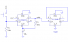
Well, i built this circuit(see attachment) to be used in a switching application. I used the same values of components as given in the schematic except the Electrolytic cap--i used 1uF instead of 0.1uF coz i had that by me then. Vcc in my case is about 8.4V. The problem is that the output pin is always at a Pd of 0V across Ground 8.5V across Vcc--even after pressing the switch. Please help
 

Attachments

  • 4013latch.gif
    4013latch.gif
    5.7 KB · Views: 2,314
Well i eventually made it work, somewhat. But once it gets latched it doesn't get unlatched. Any way 2 make this circuit act as atoggle switch?
 
apakhira said:
Well i eventually made it work, somewhat. But once it gets latched it doesn't get unlatched. Any way 2 make this circuit act as atoggle switch?
The RC network on the clock input is necessary to debounce the switch. Otherwise, the flip-flop will toggle several times each time you depress the switch.
Here's the rub - some mfrs (Philips, maybe others) have a Schmitt trigger on the clock input, so the clock is insensitive to transition times. Unfortunately, others (ON Semi, National, Fairchild, ...?) do not use Schmitt trigger clock inputs, and the specified maximum risetimes are around 5 - 10 microseconds. With the posted schematic, the risetime will be around 20 milliseconds. If you used 1uF, it will be 200 milliseconds!
As I said, you have to have some sort of clock debouncing. You can do this separately with an additional circuit, get an HEF4013 from Philips, try to find a Schmitt CD4013 from another mfr, or use another scheme which is insensitive to switch bounce.
 
Fine. I tried holding the switch pressed 4 a whole second. It switches on fine. But then the damn output(Q) refuses 2 change back to 0. Why?
And do u mean i can't have rebouncing just with an RC network.
Could u also post the formula u used 2 calculate the rise time 4 network? How about if i use a 0.01uF non-polarized cap--will that work better?
How will very small cap values affect the thing?
 
apakhira said:
Fine. I tried holding the switch pressed 4 a whole second. It switches on fine. But then the damn output(Q) refuses 2 change back to 0. Why?
And do u mean i can't have rebouncing just with an RC network.
Could u also post the formula u used 2 calculate the rise time 4 network? How about if i use a 0.01uF non-polarized cap--will that work better?
How will very small cap values affect the thing?
The risetime is approximately 2.2 times the RC time constant, which on your schematic is (100k*0.1uF) 10 milliseconds. Switches typically bounce for a few milliseconds, so a short time constant will not debounce the switch.
 
apakhira said:
and about my problem?(not going to 0 state)?
Ron H explained the reason in his first post. I quote "Here's the rub - some mfrs (Philips, maybe others) have a Schmitt trigger on the clock input, so the clock is insensitive to transition times. Unfortunately, others (ON Semi, National, Fairchild, ...?) do not use Schmitt trigger clock inputs ....."

As he said later, you need to either buy a Flip Flop that has a Schmitt trigger in the Clk input circuitry, or use the one you have but insert an external Schmitt Trigger package such as the 40106, 74C14, etc.

Also, I notice that there is no bypass capacitor shown on your circuit. You should use a 100 nF ceramic across the Vss to Vdd. Otherwise you could see strange behaviour.
 
But i think he also said that the RC network will do. Well, anyway, i have something 2 say about the RC network. See if u can explain them:
1. When i disconnect the cap, i can switch on and off normally, but there is the bouncing problem (switches on after many tries)
2. But when ithe cap is disconnected it switches off in just one press of the button. Thats no coincidence. But why?
3. When the cap is connected it switches on in one try but never switches off, even tho Vcc is going into pin when i press switch..
Why r these happening?
 
apakhira said:
But i think he also said that the RC network will do. Well, anyway, i have something 2 say about the RC network. See if u can explain them:
1. When i disconnect the cap, i can switch on and off normally, but there is the bouncing problem (switches on after many tries)
2. But when ithe cap is disconnected it switches off in just one press of the button. Thats no coincidence. But why?
3. When the cap is connected it switches on in one try but never switches off, even tho Vcc is going into pin when i press switch..
Why r these happening?
There is something internal to the design of the flip-flop that allows it to toggle high but not low when the clock risetime is slow. Are you just trying to understand why it works this way? You would have to have a schematic (which may be in the datasheet) and understand CMOS circuit design to understand this. If you are just trying to build a toggle FF, accept the fact that it won't work the way it is, and get on with life. You are whipping a dead horse, as far as I'm concerned.
 
apakhira said:
It would be good if u explained it. Umm..can the remaining Flip Flop be converted into a Schmitt trigger?
I did explain it.
some mfrs (Philips, maybe others) have a Schmitt trigger on the clock input, so the clock is insensitive to transition times. Unfortunately, others (ON Semi, National, Fairchild, ...?) do not use Schmitt trigger clock inputs, and the specified maximum risetimes are around 5 - 10 microseconds. With the posted schematic, the risetime will be around 20 milliseconds. If you used 1uF, it will be 200 milliseconds!
What part don't you understand?
You can use the other half of the 4013 to produce a clean pulse each time you close the switch. You can use this as the clock to your toggle flip-flop.
Here's how it works:
The switch still bounces, but the first closure clocks a "1" (VCC on pin 9) into the first FF.
This "1" starts charging the capacitor on the reset pin. When the voltage reaches the logic threshold, it resets the FF. The RC time constant is set so that the reset happens after the switch has stopped bouncing. The reset pin is not sensitive to rise time.
See below.
 

Attachments

  • debounce___toggle.png
    debounce___toggle.png
    10.8 KB · Views: 1,111
apakhira, If you want pure simplicity for input, take Ron's last schematic up to pin 11. All he does is create a default logic level of "0". The button when pressed will override the level and make it "1". Once the button islet go, the level returns to "0".

Aren't the chances of button debouncing lower if a small capacitor was in parallel with the button or the resistor?
 
mstechca said:
apakhira, If you want pure simplicity for input, take Ron's last schematic up to pin 11. All he does is create a default logic level of "0". The button when pressed will override the level and make it "1". Once the button islet go, the level returns to "0".

Aren't the chances of button debouncing lower if a small capacitor was in parallel with the button or the resistor?
For the two FF circuit shown, bounce is immaterial. The whole point of that first FF is to reject bounce. If you applied that scheme directly to the clock input of the toggle FF, it would seem like a good idea. However, I just don't know what the FF would do when the clock slowly returns to "0". The clock gating is done with analog transmission gates, pretty much identical to those in a 4016 or 4066. With the slow edge, I think the internal logic states may become unpredictable during the logic threshold transition.
 
What part don't you understand?
I didn't understand why a slow rise time would not work for toggling to`0' state (i wanted u 2 explain the internal cause of it). Now, about the first part of the FF circuit since i didn't have the 100n cap(C1) and a 220k(R1) resistor i did the following:
  • 1. I put a 510k resistor and 1uF cap, thinking that though the pulse time would be around 510milliseconds, the risetime would be low. But that didn't work
  • 2. Then i put a 100k resistor in parallel, making resulting resistance of R1 aroung 85k. Now, the thing acts like a mommentary on/off switch--the 2nd FF is in "1" state as long as the switch is pressed, then resets to 0. In rare cases it works. Sometimes it is even reversed and i get 0 when switch is pressed. Why?
No what do i do? btw, i presume, the simple circuit which mstechca proposes, is in the original circuit, except the pulldown resistor?[/list]
 
What kind of switch are you using? I was going on the assumption that switches only bounce on closure, but I'm finding out that some bounce on opening also. This could explain the problem you are having.
I still recommend that you use a Schmitt trigger debouncer. Do a Google search on "switch debouncing" or "switch debouncer".
 
I am using a medium-sized mommentary-on push-switch, it looks crude enough. Well, i am thinking of one thing: U said Set and Reset doesn't get affected by slow risetimes.. So if i make a one-shot pulse generator circuit similar 2 the one u had given in the schematic u posted, only with the heavily RC filter-capped signal from the switch going to the Set, will it get a clean pulse through the Q output for a reasonable time? Can it be possible?

Otherwise i have 2 resort 2 a Schmitt trigger. I wud wanna make it thru a part of a 4558 op-amp. Cud u suggest asimple circuit 4 that? But that's the last resort.
 
apakhira said:
I am using a medium-sized mommentary-on push-switch, it looks crude enough. Well, i am thinking of one thing: U said Set and Reset doesn't get affected by slow risetimes.. So if i make a one-shot pulse generator circuit similar 2 the one u had given in the schematic u posted, only with the heavily RC filter-capped signal from the switch going to the Set, will it get a clean pulse through the Q output for a reasonable time? Can it be possible?

Otherwise i have 2 resort 2 a Schmitt trigger. I wud wanna make it thru a part of a 4558 op-amp. Cud u suggest asimple circuit 4 that? But that's the last resort.
That might work. I would first try filtering by just connecting a 0.1uF cap across the resistor, so that you get fast rise times and slow fall times.
The 4013 Q and Qnot outputs will both be high when both set and reset are high, so if you don't release the switch before reset occurs, the output pulse will be longer than the switch closure time, which should be OK, as long as there are no glitches on the output.
I'm assuming you have a 4558 section that is unused. :?:
 
Ron H said:
What kind of switch are you using? I was going on the assumption that switches only bounce on closure, but I'm finding out that some bounce on opening also. This could explain the problem you are having.
I still recommend that you use a Schmitt trigger debouncer. Do a Google search on "switch debouncing" or "switch debouncer".

This issue has been discussed several times in this forum with suitable debounce circuits posted. I suggest you do a search for debounce.

Do you have a bypass capacitor across the Vdd / Vss pins as I asked some posts ago?
 
apakhira said:
What part don't you understand?
I didn't understand why a slow rise time would not work for toggling to`0' state (i wanted u 2 explain the internal cause of it).[/list]

If you look at the data sheet for the IC, you will find that the rise and fall time limits are specified. You are trying to use the IC outside these limits so it is not going to work. The internal timing of Flip Flops is critical to their operation. If the rise/fall times of the clock pulse is too slow, the state the FF goes to cannot be predicted.
 
Status
Not open for further replies.

Latest threads

New Articles From Microcontroller Tips

Back
Top