Continue to Site

Welcome to our site!

Electro Tech is an online community (with over 170,000 members) who enjoy talking about and building electronic circuits, projects and gadgets. To participate you need to register. Registration is free. Click here to register now.

  • Welcome to our site! Electro Tech is an online community (with over 170,000 members) who enjoy talking about and building electronic circuits, projects and gadgets. To participate you need to register. Registration is free. Click here to register now.

Problem with Bipolar Stepper Driver (L297 & L298)

Status
Not open for further replies.

crazybuoy

Member
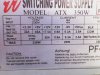
I have a bipolar stepper motor like attached motor with ~ 4kg, 3 ohm resistance per winding and 160mm x 87mm. I built L297 & L298 driver. I used 5V as power supply for motor (L298 - pin 4) and same 5V as logic voltage for both ICs. I used a computer ATX power supply for that.

It works good with stepper motor BUT the problem it that L298 turns very hot in just 10 seconds and it can blow completely after 1 minute. I did not use heat-sink yet, I just want to do experiment for this time, will add later.

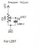
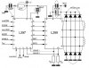
Note: I used the follow schematic and some omitted components are circled.
 

Attachments

  • L297-l298.jpg
    L297-l298.jpg
    71.4 KB · Views: 567
Last edited:
Why did you omit the capacitors? Not surprising you have problems without them.
This is what the datasheet says:-
"A non inductive capacitor, usually of 100 nF, must be foreseen between both Vs and Vss, to ground, as near as possible to GND pin. When the large capacitor of the power supply is too far from the IC, a second smaller one must be foreseen near the L298."
 
Hi alec_t,

Thanks for expert reply.

Why did you omit the capacitors? Not surprising you have problems without them.

Now I have added all omitted components. The motor turns in both direction as expected. But still the problem is same that L298n turns hot very much in just 10-15 seconds then I have to disconnect power supply. I used same power rating and power source. I use PWM (555) for stepping pulse.

Any solution to problem in circuit causing L298 turn so much hot?
How about if I build F-bridge driver using high volt & amp Mosfets?
Or you can recommend any other driver for my bipolar stepper motor.

Thanks in advance.
 
What value current sense resistors are you using and what reference voltage are you using. As you are not using a heat sink you will need to keep the current quite low as the thermal resistance to ambient without a heat sink is 35 Deg, C per watt. Bear in mind that you will have to take two Vsat voltages into consideration when doing the thermal calculations. (Note the Vsat values for this device are quite high. about 1.3 volts each.)

Les.
 
The L298 is an old driver chip. It drops ~3.2V at 1Amp and ~4.9V when used at 2A. Those internal voltage drops are why the get so hot. If your wanting to use a pin for pin newer chip a SN75441ONE will interchange in the circuit. But even that one still drops a lot and heats up. Do your self a favor and use a real stepper driver,
 
What value current sense resistors are you using and what reference voltage are you using.

The value to both current sensing resistor are same e.g. 0.47 ohm. and reference voltage to Vref (L297-15 pin) is direct 5V. I am using ATX power supply, its label is attached. I am also using same 5V as power and logic supply to L298.
 

Attachments

  • ATX power supply.jpg
    ATX power supply.jpg
    91.3 KB · Views: 207
Why did you omit the capacitors? Not surprising you have problems without them.
This is what the datasheet says:-
"A non inductive capacitor, usually of 100 nF, must be foreseen between both Vs and Vss, to ground, as near as possible to GND pin. When the large capacitor of the power supply is too far from the IC, a second smaller one must be foreseen near the L298."

The datasheet also says:-

"For motors with low winding resistances of 4 ohms or less phase resistors may be needed. Adding phase resistors should be done in equal amounts so plan to use 4 resistors. The total
resistance of the two resistors on a phase is dependent on the winding resistance."

What are these 4 resistors? Where Should I use and of how much value?

The motor winding resistance is 3 ohm. I used 5v as power supply and logic supply from ATX power supply. The image of ATX is attached in above thread. I used 2 resistors of 5 ohm 5w value as current sensing resistor.
 
You need to read the data sheets. (Or if you do not want to do that then use a circuit that has been designed by someone else.) Why have you set the current limiting value so high ? (5/0.47 = 10.64 amps.) You have exceeded the maximum reference voltage of 3 volts and you have set the limiting current to more than 4 times the peak current rating of the driver. (This limiting will never come into play as the current will be limited to less than this by the winding resistance but the device will still get very hot when operated without a heat sink.)

Edit.
I have just noticed that in post #6 you are using 0.47 ohm sense resistors but in post #7 you say you are using 5 ohm sense resistors.

Les.
 
Last edited:
You need to read the data sheets. (Or if you do not want to do that then use a circuit that has been designed by someone else.) Why have you set the current limiting value so high ? (5/0.47 = 10.64 amps.) You have exceeded the maximum reference voltage of 3 volts and you have set the limiting current to more than 4 times the peak current rating of the driver. (This limiting will never come into play as the current will be limited to less than this by the winding resistance but the device will still get very hot when operated without a heat sink.)

Edit.
I have just noticed that in post #6 you are using 0.47 ohm sense resistors but in post #7 you say you are using 5 ohm sense resistors.

Les.

I see other L298 & L297 bipolar drivers, I think the solution is to add a voltage divider at Vref pin of L297 according to the attached image. I have have same capacitor, but what is suitable var-resistor (10K suitable?).

There are only 0.50 ohm 5w sense resistors.

Do you think that this voltage divider will solve the problem?
 

Attachments

  • L297 current limiting 1.jpg
    L297 current limiting 1.jpg
    7 KB · Views: 328
You do need a potential divider (Or a more precise reference voltage that does not rely on the supply voltage being stable.) You need to CALCULATE what reference voltage you need. You will need to do this twice as you do not seem to want to build it properly to start with. (You do not want to use a heat sink for some unknown reason.) Start by doing the thermal calculations. First decide on the maximum junction temperature you want the device to run at. From the difference between that temperature and the ambient temperature you can calculate the maximum power you can allow the device to dissipate using the thermal resistance to ambient. (I think this was 35 Deg. C per watt from memory.) When you know how much power you can dissipate you can work out how much current that equates to. (Using the maximum Vsat values.) You now calculate the required reference voltage. This will be the sense resistor value times the value of current you have calculated. You will have to repeat these calculations when you decide to build the unit properly using a heat sink. The thermal calculations are a bit more complicated with a heat sink as you need to know the thermal resistance of the heat sink and insulating washer (If used) between the device and heat sink. It would help if you gave some information about what you want to drive with the stepper motor and the torque rating of the stepper. (As you say it weighs 4 KG in your first post it must be quite large.) I would have thought the L298 is too small to drive it at near it's full rating. Also you will be limited to quite a low stepping rate with such a low supply voltage due to the effect of the winding inductance of the stepper motor. I think in most cases it is cheaper to buy a ready made stepper driver module than to build one. I used a module based on the TB6560A chip for driving the stepper motor on my 150mm rotary table. (It cot about £12.00)

Les.
 
Status
Not open for further replies.

New Articles From Microcontroller Tips

Back
Top