Continue to Site

Welcome to our site!

Electro Tech is an online community (with over 170,000 members) who enjoy talking about and building electronic circuits, projects and gadgets. To participate you need to register. Registration is free. Click here to register now.

  • Welcome to our site! Electro Tech is an online community (with over 170,000 members) who enjoy talking about and building electronic circuits, projects and gadgets. To participate you need to register. Registration is free. Click here to register now.

Problem with 5V regulated power supply + buffer

Status
Not open for further replies.

ahydra

New Member
Hi all, I would be very grateful if someone can tell me what I've done wrong here. I've got a 9V battery (or thereabouts) feeding into a L7805, which should give me a 5V output (with a couple of capacitors in the circuit - see the L7805 datasheet). I've tested this and it works.

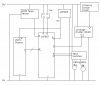
Needing to drive a PIC (16F887) and a 8-character display (AVAGO HCMS-2915) from this, I figured a buffer is needed, as I don't think the L7805 can actually supply anything more than a tiny amount of current. So I did this:

Code:
                |\ 
L7805 output -> |+\_____ 5V buffered supply
            |-> |-/ |
            |   |/  |
            |-------|

where the weird triangle thing is an opamp, 1/4 of a LM348. The LM348 is supplied from the 9V battery line (+) and the ground (-) (not sure whether I really need a negative supply - it's annoying to have to use two batteries, one connected backwards :))

I then connected this buffered output to the +LED pins of the display, the PIC and the display logic being powered by the unbuffered supply. However it seems the display causes a significant voltage drop - using a multimeter I got the following readings:

battery voltage when disconnected from the circuit 7.45V
battery voltage when in the circuit 7.0V
output of the L7805 5.0 V :) (PIC also receiving 5V)
voltage reaching the display 1.8V

I know the display is the problem because when I disconnected the -LED wire to remove the display from the circuit, the voltage reaching the +LED pins is 5V as expected.

I've also got some LEDs to show some outputs of the PIC. As the PIC shouldn't really be made to provide much current, I need to power them separately - would a 4016 work? (signal control = the PIC pin, in = 9V supply, out = fairly big resistor + LED) If not I also have some "darlington arrays" but I'm puzzled as to how these will help as they don't have their own power supply. :confused:

Many thanks for your advice,

ahydra
 
The LM7805 is a power supply. Op-amp is for signals. So however little current you think that the LM7805 can supply, the op-amp can supply even less. The LM7805 was designed to provide current to power multiple other devices...opamps are not (usually it's designed to power a single LED if it's even designed drive anything that could be considered a load at all). And uhh....if you're powering the op amp with the LM7805 well...it's still the LM7805 providing power anyways (just indirectly, through the opamp which is acting as current bottleneck and is also wasting power to keep itself running).

Your reasoning only works if you have an op-amp much larger than the LM7805, and the op amp is being powered from a supply much larger than the LM7805. But in that case, you could use any 5V input signal to the op-amp since op-amps essentially draws no current from their input source.

Buffering is for signals- where the power is not as important as the clarity, and for some reason or other the signal's original power is not able to get through because it lacks the power to do so (overcome capacitances, inductances, noise or other imperfections on the line). Buffering is not for powering things.
 
Last edited:
Buffering is for signals- where the power is not as important as the clarity, and for some reason or other the signal's original power is not able to get through because it lacks the power to do so (overcome capacitances, inductances, noise or other imperfections on the line). Buffering is not for powering things.

That wasn't the impression I got after a bit of googling - for instance see **broken link removed**

OP AMP Operation:
The circuit below shows a simple buffer circuit. The input impedance of an op amp is extremely high (on the order of 10^12 ohms). It might be used if the input signal to the op amp was coming from a source which could supply almost no current. The output of the op amp can easily drive 1000 ohms or more.

However it seems you are right somehow :) I removed the opamp from the circuit and the thing works almost perfectly - the display +LED and the chip are getting a voltage of +4.48V (not as much as I'd like, but enough).

Any hints on how to make sure we can keep it at 5V?

ahydra
 
Why not look at the datasheet of the L7805?
Its output is regulated up to a current of 1.5A.
Its output can supply up to 2.2A.
When its output current is 1A then its input must be at least 7.5V.

The opamp has a minimum output current of only 10mA then its output voltage is 1.5V less than its supply voltage.

The display uses many current-hungry LEDs. The 4 character one has a max current draw of 240mA. The 8 character one has a max current of 480mA and the 16 character one has a max current of 960mA.

A brand new 9V alkaline battery provides 7.5V and more at 400mA for about 5 minutes and provides 1A for maybe 1 minute.
But your battery was already dead when you tested with it.
 
Right, I'm not having a good time. Outside of the fact I'm down to one battery with >7.5V voltage left, my temperature sensor (LM35) is stopping the entire circuit working, one of my ICSP wires' ends came off making it a nightmare to reprogram the PIC, and worst of all the right-hand half of my display appears to have broken. It just doesn't light up.

That display wasn't cheap :( I'm not even sure how I managed to break it - why does the other half still work fine?

As for the LM35 issue, when I connect it to the regulated 5V supply it only lets 1.8V reach the display. When I connect it to the 9V supply a mere 0.3V or so gets to the display... :( I had this thing working before, but I guess that was without other loads on the circuit. At this rate I'll need 3 separate power supplies!

ahydra
 
It is time for you to attach the entire schematic diagram of your project. PNG or GIF format is preferred.
 
Last edited:
It is time for you to attach the entire schematic diagram of your project. PNG or GIF format is preferred.

Sorry, not sure this will help very much - I already described all that is wrong. Also I don't have any software to create nice-looking schematics.

Here's a rough block diagram. The arrows on the PIC and display are meant to show whether the signal is coming in or out. I missed some trivial things that are actually in my circuit, like resistors on the LEDs and capacitors in the crystal circuit. The 4040 has a 10k resistor to ground on the unused input, and the switches also have 10k resistors to prevent any random signals. (Note that the switches are connected to the 5V supply not the 9V - oops).

As stated above the temperature sensor completely breaks my circuit whether I connect it to the 5V or 9V supply. I'm not sure really what I can do about this - I guess it needs an independent supply of some sort, even if that means having another battery :)

ahydra
 

Attachments

  • clock.png
    clock.png
    18.2 KB · Views: 213
Last edited:
The regulator is designed to stay at a constant 5V as much as possible. THat's what it was designed for.
 
Right, I'm not having a good time. Outside of the fact I'm down to one battery with >7.5V voltage left
Did you measure that with the load connected?

The voltage will drop significantly on load.
 
1. Connect the 32768 Hz crystal directly to TIMR1 's osc and you can get rid of the 4040.
2. Connect the LEDs directly to the PIC (It can easily drive LEDs) gets rid of the weak 4016
3. Get a programmer with debug support like a PICkit2 and maybe you wont need the debug LEDs

Warning, the 7805 and everything else will heat up the LM35 and skew your temperature readings if they are on the same PCB or anywhere near each other.
Also the expensive 2915 LED display will chew through batteries in no time at all. An LCD will draw much less current. I built a thermostat prototype using a 16F917 with built in LCD glass driver and it works like a charm.
 
Last edited:
You don't need 3 power supplies. You need just one that is strong enough to drive your current-hungry display. A brand new little 9V battery will drive it only for a couople of minutes and your dead battery won't.

Look at the datasheet of the LM35. Its supply current is almost nothing. Look at the datasheet to see that maybe it is connected backwards so of course it uses a very high current and might be destroyed.
 
Did you measure that with the load connected?

The voltage will drop significantly on load.

No I didn't - thanks. My current status is that only half the display works :( The unloaded voltage is 8.15V, the voltage on load is about 4.9 V :( and 3.3 of that is finding its way to the display and PIC.

1. Connect the 32768 Hz crystal directly to TIMR1 's osc and you can get rid of the 4040.
2. Connect the LEDs directly to the PIC (It can easily drive LEDs) gets rid of the weak 4016
3. Get a programmer with debug support like a PICkit2 and maybe you wont need the debug LEDs

1) My program is already 1000+ lines long but thinking about the way I implemented the crystal input I'm beginning to think you have a good idea there. :) TMR1 can count away in the background and I can poll it when necessary, all I need is to reconfigure the pin as I've already used RC0 for something.

2, 3) I noticed the voltage supply to the PIC was dropping, so I thought it best to supply the LEDs from another source. I don't have a debug programmer, when the Pickit 3 comes out I'll probably get one of them.

Warning, the 7805 and everything else will heat up the LM35 and skew your temperature readings if they are on the same PCB or anywhere near each other.

They seem to remain cold - I'm using breadboard atm so this won't be a problem until I come to build the thing on a PCB (I would like to eventually make this a proper project).

Also the expensive 2915 LED display will chew through batteries in no time at all. An LCD will draw much less current. I built a thermostat prototype using a 16F917 with built in LCD glass driver and it works like a charm.

Yep, I should think (if my display ever decides to work again T_T) that this would have to be mains-powered. In the meantime I'll get an LCD display. You guys have any favourite displays - preferably one you can fit into a breadboard? Just looking at Farnell's selection now.

Look at the datasheet of the LM35. Its supply current is almost nothing. Look at the datasheet to see that maybe it is connected backwards so of course it uses a very high current and might be destroyed.

Yea I noticed it was 60uA. I'm certain I've got it the right way around :) and I don't dare connect it the other way just to test it...

Many thanks for the advice guys, I'll get this thing working eventually!

ahydra
 
Last edited:
No I didn't - thanks. My current status is that only half the display works :( The unloaded voltage is 8.15V, the voltage on load is about 4.9 V :( and 3.3 of that is finding its way to the display and PIC.
Power it from a 9V 600mA wallwart instead of a 9V battery and it will probably be fine. The display needs a minimum of 4V for the LEDs and 3V for the logic so it's not surprising that it works half assed on 3.3V ;)
If you are hung up on using batteries, use 6 AA alkalines or 7 AA NiMhs in series.
 
Last edited:
To give decent battery life 7 alkalines would also be advisable. Alkalines quickly drop to the same voltage as NiMHs and you want the output to remain at 5V when the input drops to 1V per cell.
 
Power it from a 9V 600mA wallwart instead of a 9V battery and it will probably be fine. The display needs a minimum of 4V for the LEDs and 3V for the logic so it's not surprising that it works half assed on 3.3V ;)
If you are hung up on using batteries, use 6 AA alkalines or 7 AA NiMhs in series.

I just tried using 3 AA batteries connected directly (no 7805). The chip and display receive 4.5V but the right-hand half of display is still broken. I've definitely damaged it somehow - no idea how though.

This leaves just two questions, first why the 7805 isn't providing 5V (not enough input voltage?) and secondly can someone recommend me a good LCD display (2x16 chars) and how to connect it to a breadboard (solder on some ribbon cable?)

Oh, and possibly if I am to get a wallwart, is there any alternative to chopping the output plug end off (to get at the +/- wires) if I'm using breadboard?

Thanks once again.

ahydra
 
A typical 7805 needs at least 7V to work. You'll need lots of AA (at least 6) batteries to get it running.

Better yet buy a 5V regulated switch mode wall adapter, you won't need the 7805 then. Just cut the end off if you want to solder to your kit.
 
Last edited:
with three AA cells, why not just omit the regulator?

Most PICs can withstand 6.5V for sort lengths of time so you could probably use four AA cells would be fine, but check the datasheets of alll the ICs before tying it.
 
with three AA cells, why not just omit the regulator?

Most PICs can withstand 6.5V for sort lengths of time so you could probably use four AA cells would be fine, but check the datasheets of alll the ICs before tying it.

If you read my post again you'll see I did omit the regulator :) it wouldn't work anyway trying to convert 4.5V into 5V.

Overvoltaging the PIC doesn't sound like a good idea, and it works fine with 3 AA batteries. Since the crystal circuitry also works at this voltage I'll try and get a 5V PSU or something like blueroomelectronics said.

I've got the other half of the display back - well, sort of. If I put a logic 0 on the BLANK input (pin 19), the left half (only) of the display works. If I put a logic 1 there, the right half (only) works. This isn't what's meant to happen - the BLANK input either blanks the entire display or none at all... so I'm taking this to mean that the display is damaged. If anyone does know how to fix this, I will send many e-hugs (or whatever you prefer) :D

ahydra
 
I've got the other half of the display back - well, sort of. If I put a logic 0 on the BLANK input (pin 19), the left half (only) of the display works. If I put a logic 1 there, the right half (only) works.
That sounds very strange. Make sure that all the display grounds (LED and Logic) are connected properly. You might want to double check this with an ohmmeter to rule out any breadboard problems.
Also, make sure that the 5V supply rails are properly bypassed with some 0.1uF caps and a 22-100uF cap as well.

There don't appear to be any issues with connectivity (half an ohm max between the supply rails and the connections). What do you mean by "bypassed" - connect the 0.1uF caps between the +V and 0V lines of the PIC and the display? Where does the bigger cap go?

I'm going to rebuild the entire thing after seeing some very strange behaviour. Will let you know what happens.

Thanks,

ahydra
 
Status
Not open for further replies.

New Articles From Microcontroller Tips

Back
Top