Continue to Site

Welcome to our site!

Electro Tech is an online community (with over 170,000 members) who enjoy talking about and building electronic circuits, projects and gadgets. To participate you need to register. Registration is free. Click here to register now.

  • Welcome to our site! Electro Tech is an online community (with over 170,000 members) who enjoy talking about and building electronic circuits, projects and gadgets. To participate you need to register. Registration is free. Click here to register now.

Problem while designing PCB with Eagle

Status
Not open for further replies.

cuauhtle

New Member
Hi all,

I have read variety of topics created earlier but I could not find any topic matching with my problem. So I had to start a new topic.

I am designing a printed board using Eagle-LITE edition.

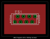
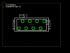
My problem is that, while I use the Polygon feature, program leaves a gap of 1mm between the polygon and dimensions automatically. Although I went over nearly all settings, I was not able to vary this distance.

There is an image here for clearance:
Imageshack - samph

Thanks in advance,

I wish a happy new year to all.

cuauhtle.


**broken link removed**
 
Last edited:
The polygon will be separated from the dimension lines by the setting specified by the isolate setting (under change). If your polygon lines are the same as the dimension lines you should be able to delete the dimension lines and the polygon will go to full size.
 
What you could do is replace the border with a trace in the same layer as your polygon. Do it at the thinnest line setting. Use the name command to set this new border as the same Net Name. The border and the polygon should then merge. I haven't tried this, but it shoulod work. Have a great New Year
 
You should be able to lay a thick wire around the inside edge of the dimensions layer and name it the same as the polygon. Not certain why this is important though.
 
Where is the problem?

Draw the polygon directly onto the dimension layer(20) using wire width zero. Perform "ratsnest" after having given the polygon a name (e.g. GND) and the ground fill will leave no space to the dimension layer.

Check attachment.

Boncuk
 

Attachments

  • 0-edge-01.gif
    0-edge-01.gif
    8.7 KB · Views: 394
  • 0-edge-02.gif
    0-edge-02.gif
    11.9 KB · Views: 427
Thanks for all replies.
I know it is not a major problem but I just wanted why program leaves such a blank.

Where is the problem?

Draw the polygon directly onto the dimension layer(20) using wire width zero. Perform "ratsnest" after having given the polygon a name (e.g. GND) and the ground fill will leave no space to the dimension layer.

Check attachment.

Boncuk

I did exactly as you said but I think somethings are different in our versions or something.
Here:
 

Attachments

  • 13.PNG
    13.PNG
    13.6 KB · Views: 314
  • 12.PNG
    12.PNG
    14.4 KB · Views: 248
I'm getting space as well when I do that with width 0 polygonl. My 'wire' method doesn't work when you surround the whole board. It kills the polygon for some reason.
 
Polygon fills follow the Design Rule for the Distance setting. Change it to something small and your polygon will fill (almost) to the dimension. Change it to 0 and the polygon can fill past the dimension.
 
Polygon fills follow the Design Rule for the Distance setting. Change it to something small and your polygon will fill (almost) to the dimension. Change it to 0 and the polygon can fill past the dimension.

Changing "Distance" in the "Design Rule Check" to 0 worked.
Thank you.


cuauhtle
 
Status
Not open for further replies.

Latest threads

New Articles From Microcontroller Tips

Back
Top