Continue to Site

Welcome to our site!

Electro Tech is an online community (with over 170,000 members) who enjoy talking about and building electronic circuits, projects and gadgets. To participate you need to register. Registration is free. Click here to register now.

  • Welcome to our site! Electro Tech is an online community (with over 170,000 members) who enjoy talking about and building electronic circuits, projects and gadgets. To participate you need to register. Registration is free. Click here to register now.

Problem using a N-channel mosfet as a switch

Status
Not open for further replies.

chunkymunky

New Member
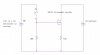
I am making a switch using a N-channel mosfet in enhancement mode, this switch must be able to close very quickly, as it is being used in a simple low voltage pulse generator that uses a piece of coaxial cable as a transmission line. The complete circuit should be attached to this post.

The voltage supply for the circuit is being supplied by 9v batteries. From what I have read, to get the Mosfet to act as a short circuit (minimal resistance) such as when a switch is closed it needs to be in the ohmic region and to do this the equation is used:

Vds<Vgs - Vgs(th)

So as the hopefully attached circuit diagram shows, I have applied a voltage of 18v the gate and 9v to the drain as I think this should satisfy the equation as the threshold voltage is low.

This works perfectly when the 50Ω is not connected to the negative terminals of the circuit, as this gives a voltage across that is equal to the 9v on the drain. However, when I do connect the 50Ω resistor to the negative terminal, there is voltage of about 2v lost across the transistor and only 7v on the 50Ω implying it is not in the ohmic region and has a notable resistance. This is important in a pulse forming circuit as it must have a load that is matched to the impedance of the transmission line being used and any extra resistance would have a bad effect on the pulse generated.

So my question is, does anyone know what I am doing wrong in the way I am using the mosfet as a switch?

Any help would be very much appreciated.
 

Attachments

  • Pulse generator &#99.JPG
    Pulse generator &#99.JPG
    54.2 KB · Views: 810
  • N-fet switch..JPG
    N-fet switch..JPG
    41.6 KB · Views: 1,693
How long do you expect a 9V battery to supply enough current to power a 50Ω resistor?

Look up the internal resistance of a 9V battery.
 
Thanks for the reply,

The battery is only used to charge up the coaxial cable used as a transmission line, which is then discharged through the 50R resistor and hopefully creating a pulse. So the battery is only used very briefly, so shouldn't use much current. I hope this answers your question.
 
Ok, then should the 50Ω load resistor be in the Drain lead, or in the Source lead of the NFET?
 
The 50Ω resistor needs to be in the source of the NFET so when the it effectively closes it discharges the voltage across it, and therefore hopefully making a pulse.
 
But then the FET is acting as a source follower, and the slew rate of the cannot be any faster than the slew rate of the gate signal. Are you trying to suddenly connect a 50Ω termination to the coax, or are you trying to short it?
 
I think I am using the 50Ω as a termination to the coaxial cable.

Then put it in between the coax center conductor and the drain of the Fet, with the Fet source tied to ground.

My question had to do with how is your "time domain reflectometer" supposed to work?

1. You charge the coax cable to 9V using a high-z source at the distal end.

2. You suddenly connect a 50Ω termination resistance at the proximal end.

3. The 50Ω termination creates a 2:1 voltage divider against the cable impedance, causing a downward step from 9V to 4.5V.

4. The step propagates to the distal end, and because the termination there is high impedance, the downward step reflects (almost 100%) and propagates back to the proximal end.

5. That causes the voltage at the proximal end to step downward to zero.

6. The time between the original half-step to the final half-step is proportional to the length of the cable, and is effected by the velocity factor of the cable.

In order to make this work right, you need to add a high-value resistor, say >10K between the 9V battery and the center-conductor at the distal end! Otherwise the reflection will not be 100%
 
Last edited:
Doesn't having R3(50 Ohm) between the source and ground make the Mosfet a high side switch? It would then need 27V on the gate to fully turn on. Correct?
 
Yes, you are completely correct in how the circuit is supposed to work and in the circuit I have made there is I think a 1MΩ resistor at the distal end. This circuit is hopefully a stepping stone to making a Blumlein pulse generator.

The problem is still trying to get the mosfet to work correctly as a fast closing switch.
 
Doesn't having R3(50 Ohm) between the source and ground make the Mosfet a high side switch? It would then need 27V on the gate to fully turn on. Correct?

To be honest i'm not sure, but the mosfets I have got the maximum gate I can apply is 20V so I don't think I could do it.
 
...
The problem is still trying to get the mosfet to work correctly as a fast closing switch.

That is a drawback of a Mosfet; it has high gate capacitance. It takes almost an infinite current to charge the gate capacitance quickly. You might be a lot better off using a small-signal NPN switching transistor like a 2n3904.
 
That is a drawback of a Mosfet; it has high gate capacitance. It takes almost an infinite current to charge the gate capacitance quickly. You might be a lot better off using a small-signal NPN switching transistor like a 2n3904.

Thanks for the suggestion, I had a look at the data sheet to see what the turn on time would be and it seemed to be around the 70ns mark which I think would be too long to get a nice pulse.
 
You dont care how long it takes to turn on (delay); you care about the rate of turn-on once the drain/collector begins to move. I still think an NPN will produce a larger dV/dt than a MOSFET. That might not be on the datasheets, so you might have to actually measure it with a high-speed scope.
 
Status
Not open for further replies.

New Articles From Microcontroller Tips

Back
Top