Hello
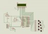
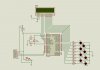
I try to program pic18F452 with MPLAB ICD3. In the pic18f452 LCD.zip i have upload the code that i modified from Wond3rboy's code and simulation with Proteus pro 7. I work with MPLAB IDE v.8.60 and MCC18 compiler.
In Simulation it works with some problems (Didn't display all the string ).
When i try to program pic18F452 in target with ICD3, i use ICD3 as a programmer with Built Configuration in "Release" mode and i have this message:
Programming...
Programming/Verify complete
I also change ICD3 as a debugger with Built Configuration in "Release" mode and program again and then i turn with Built Configuration in "Debug" mode and i press run and i have this error:
MPLAB ICD 3 detected
Connecting to MPLAB ICD 3...
Running self test...
Self test completed
Firmware Suite Version...... 01.26.33
Firmware type......................PIC18F
MPLAB ICD 3 Connected.
Target Detected
Device ID Revision = 00000007
Programming...
Programming/Verify complete
Running...
ICD3Err0040: The target device is not ready for debugging.
Please check your configuration bit settings and program
the device before proceeding.
I check my configuration bits. I read in the section Debug Failure Actions (Troubleshooting>Error Messages> Debug Failure Actions) in the MPLAB ICD3 help. But i don't know what i am doing wrong.
I also try to use MPLAB ICD2 but i have i similar error:
Connecting to MPLAB ICD 2
...Connected
Setting Vdd source to target
Target Device PIC18F452 found, revision = c0
...Reading ICD Product ID
Running ICD Self Test
...Passed
MPLAB ICD 2 ready for next operation
Resetting Target
MPLAB ICD 2 ready for next operation
Programming Target...
...Validating configuration fields
...Erasing Part
...Programming Program Memory (0x0 - 0xE3F)
...Loading DebugExecutive
...Programming DebugExecutive
...Programming Debug Vector
...Programming RSBUG
Verifying...
...Program Memory
...Debug Executive
...Debug Vector
...Verify Succeeded
Programming Configuration Bits
.. Config Memory
Verifying configuration memory...
...Verify Succeeded
Connecting to debug executive
ICD0083: Debug: Unable to enter debug mode. Please double click this message for more information.
MPLAB ICD 2 ready for next operation
Also i have try with pic18f4520 but i have the same error.
When i power on the target the LCD must turn on?
Does someone know why i can't program the pic?