bhuvaneshnick
Member
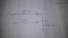
i dont know how to ensure that two diode are conducting .my professor said to remove the diodes and find the current direction ,if the current direction of branch matches with reference current direction of diode then it is on else it is off.Is that way to ensure the conduction of diode or any other way we have