Continue to Site

Welcome to our site!

Electro Tech is an online community (with over 170,000 members) who enjoy talking about and building electronic circuits, projects and gadgets. To participate you need to register. Registration is free. Click here to register now.

  • Welcome to our site! Electro Tech is an online community (with over 170,000 members) who enjoy talking about and building electronic circuits, projects and gadgets. To participate you need to register. Registration is free. Click here to register now.

Problem: How can i connect 2 switches to 1 motor without burning it?

Status
Not open for further replies.

Fluence

New Member
Hi!

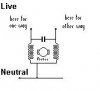
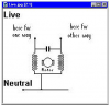
Since a image is worth more than words, here it is:

**broken link removed**

I've been thinking in the last hour in a solution to this problem, but i just can't come with something that will solve this...

It would be easy if the switches were like press-and-hold buttons, but they'r not. D:
 
Last edited:
But that way the system doesn't work properly, for example, if i had the main switch down and i activated the secondary switch with up, it wouldn't go up, because the main switch, switched off the up circuit.
 
What exactly are you trying to do? You have a motor with an Up/Down and you want to be able to switch the Up/Down locally and remotely? Your drawing could have been a little better. I see a ground, neutral Up and down. So the motor has a neutral and then line is connected to either up or down? Would that be the case? Having the motor running up and then hitting a hard down is OK for the motor? How about an Off position?

Ron
 
The motor uses: Ground, Neutral, 1 Power Line to go Up and another Power Line to go Down.

If i hitted down when the motor was going up, it would burn.
But the "secret", it's the switches.
When the button UP is pressed on the switch, automatically (via mechanical ways) the DOWN button is changed to off.
 
Last edited:
Hi Fluence,

I accept that you speak English,
better than i speak Portugese.

But it is not good enough to describe with brief sentences.

To understand what you say, please say it more ways.

Use more descriptions of your problem, to be understood.

Ok.

------------

**broken link removed**
(still trying to display pictures, i feel such a twit)


Your description of the motor is inadequate,
so based on the circuit you have given,
i have presumed it is like the one shown below.

Live.jpg (shown below, cos i cant figure out how to show it here)

If it is arranged like this,
then it can not be reversed while in motion.

While its going, it can not be driven the other way.

It cant be driven into reverse when its running.

------------

This type of motor has to be stopped before going the other way.

Before reversing direction, this type has to be stopped.

To go the other way, this type of motor has to stop first.

------------

If you want to direct this motor from two locations,
you will need the relays to have a little sequence of actions.

To control the motor rotation from two different places,
the relays will have to do a small series of events.

------------

First,
to cut motor power,
to switch motor off,
to remove motor supply.

------------

Maybe also short to assist stopping.
Might connect loading to motor to help stop motion.
Shorting or loading may be desired to help stop motor.

------------

Then,
short period allowed to ensure stopped.
No action for small time for motion to cease.
Allow time to stop.

------------

Then,
apply drive in new direction.
connect supply for other way.
replace motor power in reverse.

------------

XXXXXXXXXXXXXXXXXXXXXXXXXXXXXXXXXX

In circuits i have made to do this in the past,
i have used capacitors to hold relays for short intervals,
to allow the motor to stop.

In the past i have used capactors with relays to do this job.

------------

A modern way would probably use press buttons and a PIC to set
the intervals and operate the relays to suit the buttons.

You might choose to use a PIC with press buttons
to drive relays for timing and controlling the motor.

------------

To do this with simple relays and switches might not be possible,
and you would need to have DC to use capacitors for timing.
I think you would have to use press buttons for control switching.

If you want to use simple relays and press buttons,
you will have to include a DC supply for the timing capacitors.
Such a circuit would be quite involved.

------------

See what others say, as there are many ways to get to Rome.
Someone may know a way that suits you.

------------

Regards, John :)
 

Attachments

  • Live.jpg
    Live.jpg
    4.4 KB · Views: 236
Last edited:
I know how to make this work with simple relays.

But i need to make some "system", that when the relay is activated, it is activated only for 30 seconds maximum, and then it turns the relay off.

When i turn on the switch the relay receives power and activates for 30 seconds maximum;
When the 30 seconds had passed, the relay deactivates.
If i turn the switch off when (for example) 3 seconds had passed, the relay must deactivate. (this is why maybe using capacitors doesn't work)

Do you know how to make this "relay timer"?
 
it is the perfect application using a pic, it could be done also with 555 timers but a lot more complicated
 
I know how to make this work with simple relays.

This would be a start.
Please show how you would do this.

Also,
is the motor as shown in the attachment (post #6)

John :)
 
They make relays with 'delay on' and 'delay off'. Here is one of many companies; Time Delay Relay TDR

Google for 'time delay relay' They are common in industrial settings.

Multiple "ON" switches for motors and machines are not a good idea and may be illegal. Multiple "OFF" switches are OK.
 
Last edited:
This is how it would work with a simple relay:

**broken link removed**

But i need "something" to act as a 30sec timer, i don't mind if it's PIC, i just need a solution, then i would adapt the rest.
All the wires got 230Vac.
 
thank you.
looking at it now.
*
Is the motor as shown in the attachment (post #6)
*
If not, describe it.

John :)
 
I don't know why, but i can't see that attachment you're talking about. D:

Anyway, the motor uses a Neutral and 2 230Vac Lines.
When the Up Line receives 230Vac, the motor goes up.
When the Down Line receives 230Vac, the motor goes down.
 
I have converted it to a PNG,
as i assume you can see the pics you have posted,
which are PNG.

Can you see this Ok ?
 

Attachments

  • Motor.PNG
    Motor.PNG
    42.9 KB · Views: 175
I have tried to follow what you are trying to do, but can't, first what voltage are you using, is it one voltage or two voltages, positive or negative or both? Second, what type of motor are you using, ac, dc, permanent magnet? Third, what are you using this for an elevator or what? Forth, are you limited to the type of switch you can use, are you limited to the relays you can use. Can you use regular industrial stop start stations, if so, you can have as many start stop station that you want.
Kinarfi
EDIT, is it correct to assume that the 230 volts you are using is not two separate voltages, but the source voltage for you operation. Plus, post # 11 showed up while I was typing this one.
One more detail, how much current is needed, what's the horse power / kw rating of the motor, is it single phase or 3 phase, is it an induction motor or a brushed motor?
 
Last edited:
Will this do?
 

Attachments

  • Untitled2.png
    Untitled2.png
    46.1 KB · Views: 174
Last edited:
I don't think you must focus the motor.

The motor it's just a simple AC motor, that turns on when there's current on it's respective Up or Down line.

It's to open and close windows shutters on my house.

The motor just needs 230Vac in one phase to work. (it's single phased btw).

The only problem i have right now, is to build a system that works as a 30 second timer, just that.
I imagine it would be easy to do it with low voltages, but the system to work i can only use 230Vac.

About that picture of the motor, yeah, i think it's like that.
 
o_O can you explain me better that schematic kinarfi?

I'm looking at it but i'm not understanding it. D:
 
Thanks, good information, here's another drawing,
you can have as many remote stations as you want, it only needs 3 wires from station to station + the ground wire.
 

Attachments

  • Untitled2.png
    Untitled2.png
    48 KB · Views: 166
Last edited:
o_O can you explain me better that schematic kinarfi?

I'm looking at it but i'm not understanding it. D:

did the last picture make sense, our posts are passing each other while we type
 
Status
Not open for further replies.

Latest threads

Back
Top