Continue to Site

Welcome to our site!

Electro Tech is an online community (with over 170,000 members) who enjoy talking about and building electronic circuits, projects and gadgets. To participate you need to register. Registration is free. Click here to register now.

  • Welcome to our site! Electro Tech is an online community (with over 170,000 members) who enjoy talking about and building electronic circuits, projects and gadgets. To participate you need to register. Registration is free. Click here to register now.

problem building a frequency counter

Status
Not open for further replies.

mdanh2002

Member
Hi,

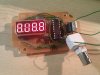
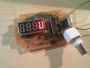
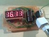
I am trying to build a frequency counter following the instructions at Frequency counter with PIC and 4- to 5-digit LED display. I am using Variant 2, with a PIC16F628A. My 7-segment common anode display only has 4 digits, so I remove the part to control the 5th digit (including R10, D1, D2, D3, D4 and transistor T1) from the diagram.

I build it on a veroboard. Unfortunately, it does not work properly. Upon power on, the display shows a single digit "8." for 1 second (to indicate initialization), followed by "***0" where * represents the top half of a "0". See the following photos. I notice the top half of the display is slightly brighter than the bottom half.

**broken link removed**

**broken link removed**

The display seems to be counting the input frequency properly, although some segments cannot be displayed.

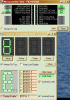
Upon investigating the PIC output with an oscilloscope, I notice something really strange:

+ Output of pin RA1 to control digit #4 is either 0 or 5V with no display connected, but drops to either 0 or 2.5V with the display connected.
+ Output of pin RB5 to control segment G is correct when the display is not connected, but always stay at 5V with the display connected.

I have checked all connections and despite the messy wiring, there seems to be no problems. Yet I could not get it working. Could it be because I am using the "A" version of the PIC, or perhaps because the PIC does not provide enough current to drive the display?

Any advice is appreciated. Have been spending my whole Sunday on this.

Thanks.
 
Last edited:
hi,
Are you sure that you have the segments/common pins of the LED's correctly orientated. ie: check the pin assignments on the LED's against the
datasheet.


EDIT:
I assume you added the 4 links to the LCD in the version 2 as shown on version 1..??
 
Last edited:
Yes, I have checked it a few times. I am using this 7-seg display array:

**broken link removed**

I believe the fact that "0" and "8." are displayed properly suggests that all wiring are correct since all LED share the same pins for their segments. There are 4 selection pins for D1..D4 and 7 pins for A, B, C, D, E, F, G, DP. I checked with an oscilloscope, the first 3 zeros are missing the bottom half because somehow when the display is connected, if D1, D2, D3 is high, somehow the pins for segments E,D,C always remain low. Something really strange must be happening...
 
hi,
I assume you added the 4 links to the LCD in the version 2 as shown on version 1..??

No. Both are using the same version. The first image is what the display shows for about 1 second after power up (I assume this is to indicate initialization), and the second image is what it shows for the rest of the time.
 
No. Both are using the same version. The first image is what the display shows for about 1 second after power up (I assume this is to indicate initialization), and the second image is what it shows for the rest of the time.

hi.
I mean the red wires that are the commons for the LED's.?

If the LED segments were incorrect , when all the segments are lit, you would still show an '8'.

Have you tried removing the PIC, then use a 330R resistor try to confirm the wiring of the LED's. Connect the common anodes of the LED's to +5V in turn and then connect the resistor in turn from each segment pin the PIC socket to 0V.
 

Attachments

  • 000esp06.gif
    000esp06.gif
    14.2 KB · Views: 303
Last edited:
Thanks for your advice. I have tested. No segments of digit 1, 2, 3 are lit using your method. For digits 4, the bottom half (segment c,d,e,g) and the decimal point (dp) are lit. I checked connections again, all seemed ok. Very strange.
 
Thanks for your advice. I have tested. No segments of digit 1, 2, 3 are lit using your method. For digits 4, the bottom half (segment c,d,e,g) and the decimal point (dp) are lit. I checked connections again, all seemed ok. Very strange.
hi,
I still suspect the LED pin outs are wrong.

Try this.
Unplug the PIC, connect LED pins 1,8,9 & 12 together to +5V

Using the 330R resistor connect LED pin11 [a] to 0V , all seg 'a's should light.

Let me know what you see.
 
Hi ericgibbs,

Thanks for your advice!

Using your method I have tested again (after resting for a day) and confirmed the wiring problem with the common pin for digits 1, 2, 3. They were confused with the pins for segment A,B,F. For a moment, I was counting the LED pins in reverse direction. This explained the weird behaviour,

Now I have got the frequency counter (somewhat) working, but I realized that it doesn't seem to count properly. Upon powerup, it shows 8.8.8.8 (lamp test) for 1 second as described, then it shows "U" as the digit (short for "undefined", or should it be 0?). Without any input connected, it would either show 16.11 (why this value?) or "U". (See attached image for more info)

My first test was to try with the oscilloscope 2V p-p 1kHz calibration output, which fails, the display would still show "U" or 16.11 (I later understood it's because the PIC16F628 does not have ADC so the frequency counter only accepts TTL signal). I tried to probe the output of a 555 timer circuit which gives 2kHz TTL square wave output, and the display still remains the same. My last try is to connect RA4 to the PIC oscillator itself, and this time the display reads 3.222 (MHz) (why, the crystal I used is 20 Mhz).

Also during some of the display transition, some digits may show U (segment A missing). it's strange because segment A is properly wired, as other digit (2, 6, 8, ...) can be displayed properly. I am not sure if this is a bug of the firmware.

See attached images. Any advice is welcome. :)
 

Attachments

  • IMG_20110117_233037.jpg
    IMG_20110117_233037.jpg
    58.1 KB · Views: 378
  • IMG_20110117_233152.jpg
    IMG_20110117_233152.jpg
    53.3 KB · Views: 265
  • IMG_20110117_233236.jpg
    IMG_20110117_233236.jpg
    58.3 KB · Views: 252
hi,
I guess you are confident that project is correctly wired.?

A quick look at the asm file from that site shows a number of conditional assembly statements.
Did you use their hex file or did you reassemble the asm file, ensuring that the conditional asm requirements were covered.??

What does it display when the count input is shorted to 0V.?
 
Hi,

I use the HEX file, counter3.hex for common anode display to be exact.

When I short the input count to 0V, the display shows U all the time. If the input count is floating, the display may switch between 16.11 (MHz) and U randomly.

I use your method to test and this time, all segments of all digits are lit properly, suggesting that the wiring is correct. If the U should have been a 0, segment A would not be connected properly. But that's not the case. Segment "A" is shown properly for other digits (2,6,8....). This makes me confident that the wiring is fine. Still not sure why a "U" would be displayed in between the digits, and why the counter is not counting properly...
 
Last edited:
Hi,

I use the HEX file, counter3.hex for common anode display to be exact.

When I short the input count to 0V, the display shows U all the time. If the input count is floating, the display may switch between 16.11 (MHz) and U randomly.

I use your method to test and this time, all segments of all digits are lit properly, suggesting that the wiring is correct. If the U should have been a 0, segment A would not be connected properly. But that's not the case. Segment "A" is shown properly for other digits (2,6,8....). This makes me confident that the wiring is fine. Still not sure why a "U" would be displayed in between the digits, and why the counter is not counting properly...

hi,
The way I read the notes with the asm file version #2 hardware requires the hex2.file.?? have you tried hex2.??

I will relook.
To make my job a little easier can you post which pins on the PIC are connected to segments 'a thru g' and the anode driver pins

EDIT:
You said you had removed the 5th digit hardware.
Look at this clip from the asm file

[CODE; Selection of LED display control bits... since 2005, three different variants.
; Select ONE OF THESE in MPLAB under "Project".."Build Options".."Macro Definitions"!
; DISP_VARIANT=1 : first prototype, PIC on left side of display
; DISP_VARIANT=2 : second prototype, separated PIC and display board
; DISP_VARIANT=3 : similar as (2), but for COMMON CATHODE display

; Unfortunately it seems impossible to assign a NUMERIC VALUE to a macro
; in MPLAB (not in MPASM!) ....
#ifdef DISPLAY_VARIANT_1
#define DISP_VARIANT 1 ; very first (old) prototype by DL4YHF
#define COMMON_ANODE 0
#define COMMON_CATHODE 1
#else
#ifdef DISPLAY_VARIANT_2
#define DISP_VARIANT 2 ; 5 digits, new layout, COMMON CATHODE
#define COMMON_ANODE 0
#define COMMON_CATHODE 1
#else
#ifdef DISPLAY_VARIANT_3 ; added 2005-03-21 :
#define DISP_VARIANT 3 ; similar as (2), but for COMMON ANODE display
#define COMMON_ANODE 1
#define COMMON_CATHODE 0
#else
#define DISP_VARIANT 4
#define COMMON_ANODE 0
#define COMMON_CATHODE 1
"Error, Must define DISPLAY_VARIANT_1, .._2, or .._3 under project options"
; With MPLAB: Project..Build Options..Project..MPASM..Macro Definitions..Add
#endif
#endif
#endif

][/CODE]
 
Last edited:
hi,
I have set up the LED as shown in the circuit diagram, it does not work with either V2 or V3. hex file.

The circuit shows RA4 as an input pin for Freq, yet its initialised as an output.
 

Attachments

  • 000esp06.gif
    000esp06.gif
    52.6 KB · Views: 241
Hi,

Finally I have gotten it working. The counting is quite precise actually. There are 2 mistakes that I made, even after I was confident that the wiring was correct:

+ Segment a and segment g output from PIC was shorted together, causing funny problems. The "U" display should have been a zero. "16.11" was probably "16.77" (MHz), displayed when the frequency is undefined.
+ The firmware has a setup mode switch (trigger by shorting RA5 to ground) which allows setting the offset frequency). I bypass the the switch but perhaps have triggered the setup mode with some random offset frequency during debugging, so the counting is incorrect. Erasing the PIC entirely and reprogramming it solves this.

Thanks ericgibbs for all the efforts to help me. I am using counter3.hex (for common anode display). Counter2.hex is for common cathode display, not appropriate for me. I will try a simulation of the circuit like what you did and see if the results are correct.

Attached are some photos of the circuit

(1) no input frequency:

**broken link removed** OK so with the board back out I started checking the gate drive circuits they are mostly on the bottom of the board, and seem to be isolated from the logic with optocouplers these to be exact https://www.electro-tech-online.com/custompdfs/2011/01/FODM452.pdf I found one that was shorted between output and ground pin I verifiyed by desoldering the ground pin and re testing it is shorted. So definitely a problem this was driving one of the shorted fets so maybe thats what took it out. here is a picture the component pointing at it with little screwdriver and gate drive circuit on the bottom of board. You can see the gate trace come down in the upper center right of picture to transistor labeled Q29. Best I can tell the opto coupler turns on the base of Q26 and Q26 turns on Q27 and Q27 turns on Q29 and Q29 turns on the gate correct? This must be a way of amplifying the gatr drive voltage to drive it high enough? **broken link removed** OK This leads me to my next question I believe the surface mount transistors on the gate drive to be these npn switching transistors http://pdf1.alldatasheet.com/datash.../BSS66.html ]Police Siren Electronic Project. The display reads 0.524 kHz

**broken link removed**
 
hi,
Thats great, thanks for letting me know, also post how the simulation works out.:)

Are you going add the transistor frequency input buffer.?
 
Last edited:
Hi,

Yes. I am going to add the input buffer, but probably not on this board. Everything looks so messy now after so much troubleshooting, and the stray capacitance is probably going to affect the counting at high enough frequency, making it pointless. When I have the time to, I am going to redo everything on a proper home-made PCB. It's very difficult to solder this circuit on a stripboard/veroboard due to the 7-segment display pin configuration.

My next target would be to try this 1 GHz Counter and connect it to an FM transmitter (for example, audioguru FM transmitter) and let it display, for example, 100 Mhz. Do you this it's possible? What disappoints me when building this circuit (and I only realized it long after I started) was that it only accepts TTL signal.
 
hi,
The 1 GHz counter looks interesting, lets know if you build it and it works as you expect.
 
Status
Not open for further replies.

Latest threads

New Articles From Microcontroller Tips

Back
Top