I'm trying to figure out how to preset an up/down counter in a way that's tied into the circuit that doesn't involve pushing buttons.
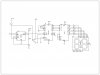
In the circuit below I've tried to create a switch that I can turn 'on' and then my counter starts at 6 and counts down, displaying the number on a 7-segment LED.
Is what I did with the transistor correct? Does it work? Does it not work? Do I need to 'pulse' low somehow instead of just holding it low and then holding it high? I'm trying to grasp exactly how you can preset a timer. Eventually I plan to put a dip switch in to make the number configurable, as well as chain some ICs to make it multi-digit, but for the time being I'm just trying to figure out how to load the number.