Continue to Site

Welcome to our site!

Electro Tech is an online community (with over 170,000 members) who enjoy talking about and building electronic circuits, projects and gadgets. To participate you need to register. Registration is free. Click here to register now.

  • Welcome to our site! Electro Tech is an online community (with over 170,000 members) who enjoy talking about and building electronic circuits, projects and gadgets. To participate you need to register. Registration is free. Click here to register now.

Preamp doesn't work?

Status
Not open for further replies.

Ventura

Member
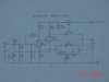
The attached preamp circuit is a reproduction of what came with the “Smart Kit No. 1024” microphone preamplifier kit that. It’s purported to be suitable for dynamic and condenser mics. I carefully soldered it together and put it in an enclosure with appropriate jacks. It didn’t work.
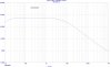
An oscilloscope (that I built from a kit) shows my dynamic mic putting out a signal, but the preamp’s output is nearly flat-line.

The outfit in New Hampshire that sold me the kit has been, frankly, a bit rude, but they eventually, grudgingly agreed to take a look at the silly thing. They said it will be low priority (nice folks, eh?), so I don’t expect a response for some time. In the meantime, I bought all new components from DigiKey, including good quality metal film resistors, and built another preamp from scratch, on perfboard, following the same circuit. It doesn’t work either.

I’m no electronics wiz, but I’ve put together a number of projects over the years, some from scratch. They all work. I can’t figure out what’s going on with this little beast. Do you guys see anything odd about this preamp? Does it look like it should work?

Thanks.
 

Attachments

  • Mic Preamp circuit drawing.JPG
    Mic Preamp circuit drawing.JPG
    817.3 KB · Views: 445
Last edited:
Sorry I can't answer your questions since I'm no good with discrete amplifiers. I just wanted to say your sketching and writing is cleaner than my printer's.
 
Gaston, I considered some op-amp circuits, but someone here told me about a simple kit for $9.50. I have a dynamic mic with unbalanced connector and this preamp is designed for that application. As this is for a security surveillance system I'm working on, I wanted to get something up and running quickly to see if the system is going to work for me at all. I had thought I might build a better preamp later. Unfortunately, I've wasted money and a lot of time on this design, and still no joy. Very frustrating....
I just wish someone could tell me this thing at least looks like it should work.

Thanks
 
i would think that an opamp, a few resistors and capacitors and you will be up and running. i'm shure when audioguru sees this he will be able to help you with your schematic. im not that good with descrete either. when i run into problems like this, where i know the circuit should work, i start checking every little detail that i did, like are the transistors face the right way. did a piece of solder bridge a trace, mabey the wrong value of a component in the wrong place ect
 
Thanks, dknguyen. Visioneer doesn't want to provide a WindowsXP-compatible driver for my scanner (it's really not all that old), so I had to take a digital photo of the paper. I'm not exactly sure why it comes out gray like that. There was plenty of light; it's some sort of automatic compensation thing the camera is doing.
I need to figure this out because I'm not inclined to buy another scanner. I'm spending my money building and rebuilding this preamp that doesn't work.
What fun....
 
Gaston, I've peered at this thing (even with magnifier glasses) until my eyes nearly failed me. The transistors Digi-Key sent me are from Fairchild. I checked and confirmed which sides are collector and emitter.
Most of the other simple preamp circuits I've seen are for balanced inputs, and/or condenser microphones. I don't want to mess with the batteries or whatever required by a powered mic, which leaves dynamic, which is what the one mic I currently own is. I might eventually consider going to a balanced output-type mic, but I think it will still be a dynamic unless it turns out that that simply won't work. For now I just need a simple, basic preamp.

Thanks
 
It looks like it should work. Take some DC voltage readings at the emitter, base, and collector of the transistors and post the results here. Also post the exact supply voltage that you are using and the DC voltage at C5.
 
For a quick check I ran a DC test on your amplifier using a 12 volt supply. I used 2N2222A transistors so things will be a little different. The numbers in pink boxes are the DC voltage.

The AC frequency response shows that it has an “audio” frequency response.
 

Attachments

  • Image2.jpg
    Image2.jpg
    98.1 KB · Views: 225
  • image3.jpg
    image3.jpg
    439.3 KB · Views: 197
The collector voltage of the second transistor is lower than its base voltage and both transistors are almost saturated.

The frequency response is not for audio because it rolls off the high audio frequencies like an old telephone or old AM radio. Listen, it doesn't have hisssss!
 
If you change R1 to a 2.2K, the bias voltages will look a bit better.
 
It does look complicated for such a simple function. I bet audioguru can come up with a better circuit using fewer components.
 
ronsimpson said:
The AC frequency response shows that it has an “audio” frequency response.

My simulation result shows a "flatter" frequency drop off response at frequency >10KHz.

Maybe it is the different transistors being used. Anyone wants to try this the .asc file is attached.
 

Attachments

  • MicPreA.asc
    3 KB · Views: 144
  • MicPA.gif
    MicPA.gif
    27.9 KB · Views: 183
Last edited:
Thanks kchriste and all for the replies. As requested, I’ve listed some voltage readings. These are all between the noted lead and ground. Is that what was needed?
Supply: Exactly 12VDC, regulated;
TR1: Collector: 1.84
Base: 1.84
Emitter: 1.24

TR2: Collector: 1.84
Base: 0.79
Emitter: 0.23

C5: 4.28

I just don't get how this company could be marketing these "Simple" kits if they don't work, but I also can't see where I did anything wrong. This is strange.

Thanks
 
Ventura said:
Thanks kchriste and all for the replies. As requested, I’ve listed some voltage readings. These are all between the noted lead and ground. Is that what was needed?
Supply: Exactly 12VDC, regulated;
TR1: Collector: 1.84 (1.73)
Base: 1.84 (1.89)
Emitter: 1.24 (1.27)

TR2: Collector: 1.84 (1.89)
Base: 0.79 (0.80)
Emitter: 0.23 (0.23)

C5: 4.28 (4.20)

The DC voltage of my simulation is shown next to yours in red. It is a very close match to your measurement and that of ronsimpson's.

I have no idea why your finished circuit won't work but it must be a very simple reason.

Edited: Also check that your dynamic mic does not put out a steady DC voltage higher than 0.8V. If there is a steady voltage higher than that, then the polarity of the input capacitor C1 is not correct. The leakage current of the capacitor will easily mess up the biasing of the circuit. If that is the case, you have to use two capacitors connected back-to-back in order to block the DC voltage from the dynamic mic, but the capacitance value need to be doubled to 10uF each. i.e. positive of 10uF cap1 joins to positive of 10uF cap2. Negative of cap1 to Tr2 base and the negative of cap2 terminal for signal input.
 
Last edited:
My first thought is to change R3 to 22k. The voltage on Q2-C went up to 3.9volts.

Thought 2. Change R1 from 6.8k to 10k. Q2-C=2.8 volts.

We need to get Q2C up to around 3 volts which is 1/2 the voltage on the 47uf cap (supply= 5 to 6 volts).
 
I have absolutely no experience with preamps, so please forgive what may come across as a dumb question:
Will a properly functioning basic preamp typically provide enough power to directly drive a set of compact/lightweight headphones? Rather than using my oscilloscope, with which my expertise is quite limited, can I just plug some headphones into the preamp's output and listen?

I did try this already, and got absolutely nothing.

Thanks
 
It should give you at least hum in headphones if nothig is heard then it is not working properly. And preamp whit this transistors shoul work fine with headphones.
 
Ron, I'm willing to make changes to try to improve this preamp's performance, but right now there is no performance...zilch, nada, dead. Something is completey out of whack. I think I should try to determine if it will work at all before I start tweaking it.
The error could very well be mine, but I sure can't figure out what I might be doing wrong.

Thanks
 
@ronsimpson,

I have figured out why the high frequency response of the Preamp circuit is flatter in my case.

Your simulated circuit is a little different from that of Ventura's regarding the 120pF output feedback capacitor connection. You have connected it to the other emitter instead.
 
Status
Not open for further replies.

New Articles From Microcontroller Tips

Back
Top