Continue to Site

Welcome to our site!

Electro Tech is an online community (with over 170,000 members) who enjoy talking about and building electronic circuits, projects and gadgets. To participate you need to register. Registration is free. Click here to register now.

  • Welcome to our site! Electro Tech is an online community (with over 170,000 members) who enjoy talking about and building electronic circuits, projects and gadgets. To participate you need to register. Registration is free. Click here to register now.

Powering Superflux LEDs with varying voltage

Status
Not open for further replies.

joe1990

New Member
Hi, I've been doing a lot of research for powering LEDs under varying voltage conditions more specifically about 10-18volts.

So far I bought twelve Lumileds amber superflux Model# HPWT-ML00, I've decided to do a 4x3 array, (4 parallel strings with 3 LEDs each string).

From what I understand in the datasheet the LEDs should be runned at 50mA-70mA with a nominal forward voltage of 2.6v @70mA.

I've seen five different ways to power the LEDs, what is the most reliable way out of the five?

1) Using a current limiting resistor in each string.
3) A circuit that uses an NPN transistor, a N-channel FET, and 2 resistors.
2) Using a LM317 regulator with a resistor between the adj and out to make it a constant current.
4) A sense pass current regulator.
5) The switching type current regulator.

I'm also curious about protection circuits, which is a silicon diode in series with the LEDs, and a zener diode wired in parallel, is this nessesary and/or helpful?

Here's some example diagrams of the above circuits.

Resistors with protection diodes
**broken link removed**

transistor circuit
**broken link removed**

lm317 regulator
**broken link removed**

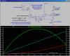
switching and sense pass circuit
**broken link removed**
 
LEDs are not voltage, but current driven. The forward might vary and adjusts itself if the LED is driven by the correct current.

So yes, a constant current source is the best way to go, leaving enough headroom for the added forward voltages of the individual LEDs.

Boncuk
 
Here is another one to add to your collection:

Constant-Current. Pot Adjustable 0 to 2A. Soft-Start and protected against a dirty pot. Can drive multiple LEDs in series if supply voltage is raised. Note dissipation in NFET and the shunt.
 

Attachments

  • HCLed.png
    HCLed.png
    51.2 KB · Views: 390
Last edited:
I made a night light with 36 Luxeon SuperFlux LEDs and operate them at "only" 53mA each. Boy oh boy they get extremely hot even though the case has many holes for cooling. If you have a single SuperFlux LED at 70mA then you will need liquid nitrogen or a high velocity fan to cool it.

Your current source shows a P-chaanel Mosfet but needs an N-channel Mosfet (its arrow points in, not out).
 
thanks for all the replies, I've decided to use the simple resistor method with the two diodes, since audioguru said that running the led's at only 53mA produces a ton of heat, the calculations are based at a more conservative 30mA, how do the resister values look? here is the schematic i drew up thanks for all the advice

Some more info: i used a voltage drop of 2.4v for the leds and 1.2v for the silicon diode.

**broken link removed**
 
The first thing this zener will do, besides being useless, is emit a puff of smoke.

Please use a constant current source to drive the LEDs. Any of the above schematics seems good.

And yes, superflux or any type of LEDs except high-power ones have very low maximum power dissipation. Besides, the thermal conductivity of the plastic case is really bad. And the light output efficiency decreases with hotter temperatures. So, I'd either use many small LEDs at their rated current (ie usually 20 mA) or use a real high power LED (like XP-G or Seoul) on a proper heat sink.

> MikeMl

Note the opamp is driving a large capacitive load, so the feedback can be delayed enouch to make it unstable. This depends on the opamp and MOSFET gate capacitance. To make the circuit really safe, you can use a capacitor between the opamp output and - input, and a gate resistor on the MOSFET. This makes the transfer function unconditionally stable.
 
Last edited:
Thanks for the advice, I've built the circuit today, and it seems to work well, i measured the voltage drop of the leds at 2.43v each, and the current was at a nice and low 35.8mA with the supply at 12.75v, although I deviated highly from my drawn resistor values because after further calculations they were much too conservative, I ended up using 150Ω resisters per string, also the electronics store did not have the 1N5406 so i substituted it for a 1N5408 which has a max reverse voltage rating of 1000v. For the zener diode my understanding is that it acts as a positive transient supressor.

**broken link removed**

**broken link removed**
 
Last edited:
Status
Not open for further replies.

New Articles From Microcontroller Tips

Back
Top