Continue to Site

Welcome to our site!

Electro Tech is an online community (with over 170,000 members) who enjoy talking about and building electronic circuits, projects and gadgets. To participate you need to register. Registration is free. Click here to register now.

  • Welcome to our site! Electro Tech is an online community (with over 170,000 members) who enjoy talking about and building electronic circuits, projects and gadgets. To participate you need to register. Registration is free. Click here to register now.

Powering 12x 1W Luxeon LEDs

Status
Not open for further replies.

mtongnz

New Member
Hey.

I have been working on this project:
**broken link removed**

It is working perfectly but I want to use it in an RGB light which has 12 Luxeons of each colour.

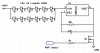
The constant current source provided on that link is the basis for the schematic I have posted. Unfortunately, the lights I am modifying have a common +24V supply, meaning I need the LM1084 on the GND side of the Luxeons.

I have worked out that with the LEDs in 2 strings of 6 should mean I need ~24V (allowing for the drop accross the LM1084) at 4.2A

I would like to know if my schematic will work as I am expecting, and if not, what modifications does it need?

I will be making a 3-5 of these circuits (RGB + maybe Amber/White) and running them from seperate PWM sources but a common power source.
 

Attachments

  • constant current 2.jpg
    constant current 2.jpg
    48.6 KB · Views: 778
You cannot run parallel strings of LEDs without limiting current separately in each string.

Lose C1; it will cause a current spike that goes through the series LEDs each time the PWM driver turns on.

If you are PWMing, why have the LM1084? It will just go crazy trying to follow the PWM pulses. When switching from zero load to ~1A load, the transient response of the LM1084 is such that it will take most of the duration of the PWM-on-time to settle to the selected current, during which the current overshoot is very large. Looking at your link, it is apparent that the guy is good at programming, but doesn't have much experience with hardware.

You would be better off just using a NFET with a current-limiting resistor between the Source and GND, and the LEDs between +24V and the Drain. If you use logic-level gate NFETs mounted on the same heatsink that the LM1084 would have to be mounted on, the cost per driver will be lower, and the performance will be better. Besides, you need twice as many of these drivers as you thought...
 
Last edited:
I was under the impression that the LM1084 was basically the same as the LM317 but with a higher amp rating. Would I be better off using the LM317?

And should I place a cap across the LED string or not have one at all?

I thought using just a resistor to limit current was frowned upon for luxeons due to the change in voltage (and thus current) caused by temperature rising. These need to be able to run for up to 8 hours without issue so I want the best solution. I dont mind a few extra components.
 
I was under the impression that the LM1084 was basically the same as the LM317 but with a higher amp rating. Would I be better off using the LM317?
No, the transient response issue is the same for a 317 or 1084, only the current rating is different.

And should I place a cap across the LED string or not have one at all?

A cap across the LED string is much better than the one you showed across the current-setting resistor inside the 1084's control loop. I dont think you need one, though.

I thought using just a resistor to limit current was frowned upon for luxeons due to the change in voltage (and thus current) caused by temperature rising. These need to be able to run for up to 8 hours without issue so I want the best solution. I dont mind a few extra components.

I didn't propose putting a resistor in series with your Luxeons; I proposed making a true current source.

Stare at the attached circuit/simulation. Note the power dissipation in the NFET and the Source resistor. The Source resistor sets the current through the LEDs, in this example, about 520mA, which causes the LEDs to be operated at 1.8W when on. I couldn't make it work with 6 LXK2-PW14 LEDs, because there was not enough voltage left over (headroom) to make the current source work. Your LEDs may have a lower forward drop, so you can use six per string.

Note the power dissipation in the NFET; it will have to be bolted to a heatsink, just like the LMxxx would have to be. The NFET should be of the "logic-level-gate" type.
 

Attachments

  • DF87.png
    DF87.png
    46.9 KB · Views: 390
Last edited:
what is the reason not to put the strings in parellel?

And I dont see how your circuit is constant current. There's no feedback loop or regulation. Does the NFET do the regulation?
 
what is the reason not to put the strings in parellel?
The forward voltage drops of LEDs are not all the same. You could wind up with twice as much current as you planned through one branch, while the other branch has almost zero current.

And I dont see how your circuit is constant current. There's no feedback loop or regulation. Does the NFET do the regulation?

Look at the rightmost simulation, where the gate voltage is held at 5V, same as a logic high from the MCU. I vary the supply voltage to see what influence that has on the LED current. Note that when the supply voltage is more than 22.8V, the current through the LEDs is very constant. Look at the Port (gate), Source and Drain voltage to see how the NFET works to keep the voltage at it's source constant, which means that the source current is constant, which in turn means that the drain (LED) current is too.

For a fixed gate voltage (5V is what I am assuming), the LED current is determined by the Vth of the FET and the source resistor R1. In the rightmost simulation, I picked R1=4.7Ω, which makes the LED current ~520mA, but you can make it anything you like by changing R1. The leftmost simulation shows the LED current for values of R1 of 3.3, 4.7, 5.6, 6.8, 8.2, 10, 22, and 33Ω, while the supply voltage is swept as before. Note that once the supply voltage is big enough, the LED current is remarkably constant.
 

Attachments

  • DF87a.png
    DF87a.png
    43.8 KB · Views: 294
  • DF87b.png
    DF87b.png
    41.7 KB · Views: 338
Last edited:
Thanks heaps for your explanations. I've tried it on a breadboard using a BUZ11 as M1 and it seems to work perfectly.

While I'm picking your brain... what is the best way to drop 24Vdc to 5Vdc as I wasnt to run the IC board from the same power supply but running it through a 7805 is really inefficient - and I would prefer to stay away from using a big heatsink on it.
 
Multi-winding transformer with a regulator fed from ~8V, or use a separate wall-wart supply for the 5V. A switch-mode DC-DC buck converter is another way.

The BUZ11 is not a "logic level" gate, so the Vth is much higher than the one I use, meaning more variability in the actual voltage drop across the source resistor if another NFET of the same part number is substituted. You could always use the "closed-loop opamp to drive the gate" method I showed in the other thread.
 
I've used Luxdrive Buck Pucks before and they work well. Everything in regards to driving the LED's is done for you - all you need to do is provide the control inputs.
 
Well I've used the original circuit you provided and a DC-DC converter and it's run for on 4 occasions for 5 hours each time without issue. It dims beautifully and all the components stay ice cold without the need for any heatsink :) I'm still waiting for the NFET you suggested to arrive but it seems to work fine with the BUZ11.

I've got 3 lots (Red, Green, Blue) of 2 strings of 6 LEDs in parallel.

I'm very happy with how well it works and can't wait til next week when I will have time to make the actual PCBs and put it all in the finalized case. I'll post images then

Thanks for all your input.
 
Status
Not open for further replies.

Latest threads

New Articles From Microcontroller Tips

Back
Top