Continue to Site

Welcome to our site!

Electro Tech is an online community (with over 170,000 members) who enjoy talking about and building electronic circuits, projects and gadgets. To participate you need to register. Registration is free. Click here to register now.

  • Welcome to our site! Electro Tech is an online community (with over 170,000 members) who enjoy talking about and building electronic circuits, projects and gadgets. To participate you need to register. Registration is free. Click here to register now.

Power transformer audio

Status
Not open for further replies.

Gregory

Member
I am rebuilding a valve amplifyer for a Seeburg 148 music box.
I have finished the rebuild of the main amp and have the pree amp to do.
I powered the main amp up with a load and every thing is ok but the audio power amp is down in resistance between the center tapping and the other two takings . Which causes a audio problem.
I am looking at punching a new transformer but the only information I have is the voltage in and out I need to find out the power rating of the transformer.
Can somewon help me with this.
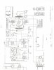
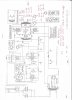
I will post a circuit
 

Attachments

  • image.jpg
    image.jpg
    890.8 KB · Views: 476
... but the audio power amp is down in resistance between the center tapping and the other two takings . .
What are you saying? Are the windings shorted to each other? to the frame? What is the resistance measured?

When primary of the transformer is powered, but with the 5U4 rectifier unplugged, what is the AC voltage at the two ends of HV winding measured with respect to the center-tap?

When the amplifier is running, what is plugged into the master speaker plug S4?
 
I will attach a circuit with the readings ? When I did the reading with the SU4G valve removed the reading was very low volts can you explain. If the valve is removed the reading would be Ac is that correct.The readings wer done with the valve in circuit. The dc voltage was done respect to ground.
The current reading was done with a clamp meter.
 

Attachments

  • image.jpg
    image.jpg
    1.2 MB · Views: 357
Last edited:
From what you say, I have some suspicions.
For example, why use a clamp meter to measure DC current when the currents are only up to about 250 mA. I wonder what test equipment you have.
If the transformer is faulty, then take it out of the circuit and apply a test signal of say 5 Volt AC from the heater supply to the output transformer secondary and use an oscilloscope to measure the voltages across each half of the primary. IF the transformer is faulty, then just get it rewound.
My guess is that with 6L6 output bottles with a 300 volt dc supply, the power rating is around 15 watts. The power supply transformer will be about a 30 watt rating for the dc supply plus about another 30 watts for the heaters. That makes about a 70 or 80 watt power transformer.
hope this helps.
 
I do not have a oscilloscope only Dmm and my clamp meter and a power supply and varyack If I can find out the power rating of the audio transformer T3 then I may be able to buy one .I am unable to buy a original one from the supplier and they do not have any specification on the audio power transformer T3 .I will try and test the AC with the recterfyer removed. As the main power transformer T1 is new. The supplier requires the power rating to be able to supply a transformer.
 
Ah, the venerable Seeburg "Trashcan". Did a complete restoration (to factory specs) of a 147 a few years ago. It's in a local seafood bar/restaurant, actually making money. The sound of that old rig is amazing.

The main xformer of the amp was shorted (tar leaking out the bottom). The only option was to purchase an original, populated (except for tubes) chassis ($125.00). Only repair needed was a complete cap replacement.

Got mine from http://victoryglass.com/

Call them (Denny) for availability and price.

Also from **broken link removed** ($45.00, no tubes, but not a bad price for a transformer of that sort).
**broken link removed**
...When the amplifier is running, what is plugged into the master speaker plug S4?

The electromagnet on the speaker, which also serves as the HV smoothing choke. Very common for the era.

<EDIT> If I misunderstood your request, the others xformers are, obviously, also on the chassis(s) I listed.
 
Last edited:
The T3 Audio transformer has
1960 turns on the primary wirer dia is .15 mm
The secondary is 86 turns 1.16 mm dia
Can you work out the current rating from this information.
 
With the T3, this is an impedance matching transformer and from the info given it is about a 5000 ohms plate to plate impedance to give an 8 ohm output impedance. The tapping for 4 ohm would be at about 55 turns at a guess. The turns ratio suggests an impedance transformation ratio of about 450 or so.
The construction of this transformer is probably using a thinner core lamination material compared to the power transformer.
The design is obviously very old because of the electromagnet field winding. This stuff was obsolete by about the 1950's or earlier when ALNICO permanent magnet material was developed.
The project seems to be hung up on whether the transformers are faulty or not. When you ask about 'power ratings', I sense you are talking to a 'new transformer supplier' and if this is the case you will likely get nowhere fast. For a restoration, and IF the transformer is faulty, a rewind is suggested.
I note you are in OZ as I am, and I can tell you that what is available in Australia today is nothing like what it used to be. Getting the kind of components you want, used to be dead easy, but now all you get is frustration. Drongos in supply houses work out of catalogs and its like talking to a brick wall. If you need another audio transformer, get the original rewound. When you find someone to do this job, you will find he is an old guy about 70, who can do stuff.
I restore and collect pianolas, and I am aware of the Seeburg company because they made orchestrions in the 1920's. They've been around a while. Much of this old stuff is getting hard to renovate and guys have to be inventive. In the US, there is a huge industry of backyarders who can do anything.
hope this helps.
 
There is a supplier in Quesland ,Evatco who can help me but requires info
Current, Hz Voltage .
On my previous post I submitted a circuit digram and the voltage is 290v dc but in brackets there is 1000 what does this mean
 
Let's start over.
... I powered the main amp up with a load and every thing is ok but the audio power amp is down in resistance between the center tapping and the other two takings . Which causes a audio problem. ...
How did you measure the resistance and did you completely disconnect ALL of T3's wires? What were the resistance values between of the windings of T3? *What windings of T3 do you suspect are defective?
...On my previous post I submitted a circuit digram and the voltage is 290v dc but in brackets there is 1000 what does this mean
The "(1000)" you're seeing is the suggested test voltmeter scale* to be used to measure the 290 VDC noted on the schematic - look closely at the "NOTES" section, line 5.

I have an extra T3. Would you like me to check its resistance values?

* <EDITED>2053
 
Last edited:
Yes please . I tested the resistance between the 3 tappings as shower on the no 3 post ,circuit digram with all wires disconnected.
Would you know the power rating af the transformer.
I will post the iron field measurement . Hight. Width . Bredth. If this is of help to you.
A to C on that circuit digram posted.
Thank you
 
Status
Not open for further replies.

Latest threads

Back
Top