Continue to Site

Welcome to our site!

Electro Tech is an online community (with over 170,000 members) who enjoy talking about and building electronic circuits, projects and gadgets. To participate you need to register. Registration is free. Click here to register now.

  • Welcome to our site! Electro Tech is an online community (with over 170,000 members) who enjoy talking about and building electronic circuits, projects and gadgets. To participate you need to register. Registration is free. Click here to register now.

Power Supply Schematic

Status
Not open for further replies.
If a power supply is oscillating,
Is the 100mV signal from the power line? 50/60hz which makes 100/120hz noise.
Or is it really oscillating, 1khz sign wave noise? (I don't know the frequency 500hz to 5khz, but not from the power line)
 
Thank you for the replies.

If I use parallel power transistors (like in the attached schematic) for a power supply (again, generally speaking) and I also use emitter series resistors for those power transistor, what is the maximum allowed difference between the current that pass through the power transistors ?
I know that this depends on the value of the emitter resistors and on the value of transistors Beta (amplification).
 

Attachments

  • parallel-BJTs.gif
    parallel-BJTs.gif
    3.7 KB · Views: 118
If a power supply has a compensation network then a high esr cap or connection going high resistance could change the freq response of the supply, and that will mismatch the compensation network and possibly make the supply oscillate.
This is also the case if you build a supply with different components or even layout than that of the original.
 
How can I estimate the current rating for a freewheeling diode for a power supply ?
For example, if the maximum output current from the power supply is 3A, then what should be the rating current of the freewheeling diode ?
I searched and found that some people are talking about a diode of minimum the output current of the power supply, while other people are talking about the peak current through a diode...
A freewheel diode is only needed in a switch-mode converter, usually a buck converter.

In the circuit that you have shown, there is a diode across the output, which stops the power supply being damaged if something causes the output to be driven in reverse. The rating of the diode depends on what can drive the output in reverse. If the power supply is just driving a simple load, the diode isn't needed. If you have two power supplies in series, then the diode needs to take the full current rating of the power supply.
 
But if I will drive a motor isn't necessary a diode on the output of the power supply ?, To protect the power supply from reverse currents generated by the motor ?
 
Last edited:
To protect the power supply from reverse currents
Many people stack two supplies to make 2x voltage or to make +12V & -12V. When stacked it is possible for one supply to supply reverse current back into the other supply.

For protection I would use a diode rated for the supply current. (not buck PWM, not freewheeling)
 
But if I will drive a motor isn't necessary a diode on the output of the power supply ?, To protect the power supply from reverse currents generated by the motor ?
My point is that the diode is there to protect the power supply from other sources of power, not from the power supply itself. Therefore the diode rating needed depends on the nature of other sources of power, not on the power supply itself.

If there are two similar power supplies in series, then a diode in parallel with each is a good idea in case one supply stops working. The current from the working supply has a diode to go though rather than damaging the failed supply. Each supply needs a diode large enough to take the current from the other supply, but as the supplies are similar, each diode's rating needs to be as large as the rating of the supply it is connected to.

DC motors can generate voltage in two ways. Firstly as an inductive spike when the current is turned off. That would be a negative voltage, but it would only last for a millisecond or so. A diode to limit that negative voltage would have to take the full motor current but only for a short time.

The seconds source of voltage is the motor generating as its inertia keeps it spinning. That can last for seconds, but it will be in the same direction as the voltage that got the motor spinning in the first place, and at a lower voltage, so a diode on the power supply output will block that voltage, as it does when the motor is running normally.
 
1) a freewheel diodes current rating on a smps depends on the design of the supply, a very approximate (wait for it) guess is to double the output current rating.
2) if your protecting a supply in a dual supply setup then the diode wants to be a minimum of the 2 supply's current added togther.
3) protecting a supply from back emf and if the motor only goes one way then place a didoe across the motor reverse biased, the current rating ought to be that the motor uses, & the voltage equal to the back emf, if you dotn know you could guess 1000v, some say that a diode wouldnt allow the bemf to go higher than 0.6v, the forward voltage of the diode, but they do not switch on instantly so your better with a higher rating.
 
1. Regarding the attached schematic, if I will use P600K diodes instead of 1N4007, for D1 and D7, it is possible that the power supply to start oscillate if I change from 1N4007 to P600K ?
I tested the schematic, and it doesn't oscillate using 1N4007.
2. Regarding the same attached schematic, if I will use 1N4007 diodes and I will power 3A motors, can the diode be damaged ? Or what could happen ?
 
Last edited:
I seem to keep digging myself holes.
Without designing the whole thing from scratch I cannot say for sure.
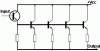
D1 if replaced might be Ok, as its just changing capacitance across the output, maybe adding a little leakage.
However D7 across the pseudo o/p tranny will change the freq response of the supply, probably not by much but a change none the less.
Kick back from the motor initially at least is the same current as the motor, as the motor has inductance and tries to maintain current flow, average power will be lower, however to have some room for error increasing their ratings is a good idea.
See if you can get a spice model for the diodes you mentioned, or suss out how to enter the params, its not that hard.
 
Hello,
I have found on the internet the attached power supply schematic.
Can you please let me know if there are any replacement transistors for TR3-TR6 (A823) and TR2 (3223) ?
The replacement transistors are not necessary to be pin to pin compatible.
Also, I would like to know the voltage for ZD3, the part number for D4 (it should be 1N4148 ?) and the secondary voltage of the transformer.
 

Attachments

  • 723_schematic.jpg
    723_schematic.jpg
    68.9 KB · Views: 130
Last edited:
Status
Not open for further replies.

Latest threads

New Articles From Microcontroller Tips

Back
Top