I did a thread about 4 month ago maybe longer on this circuit is there a way for me to find all my past threads, other forums have that option? I looked way back never found it.
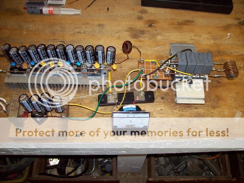
I put my circuit back together today with new improvements. I replaced the Chinese bridge rectifiers that kept self destructing at 15 amps with 40 year old bridge rectifiers that are not Chinese.
I built a dedicated power supply for each circuit. The gate circuit has a 12 VDC power supply. As I added capacitors 1 by 1 voltage kept going up until I added the 5th cap then voltage dropped. 4 caps are giving me 11.94 VDC. When I was in college we used a scope to added enough caps to get flat line DC. I wonder if 4 caps 3300uf each is giving me flat line 12VDC at 1 amp? This is working good, big improvement over what I had before.
The other power works the same 12 caps 3300 uf gives me 21 VDC. If I add or remove caps voltage drops. Adding more caps only drops .01 volts.
The circuit is working good like before 21 VDC 36 amps on the meters with a 3/8" rod in the work coil. After the rods turns red hot amps drop to about 7 amps. With no rod at all current is 5 amps. Mosfets are not even getting warm at 36 amps and I have no cooling fan. We played for 10 minutes heating all kinds of things red hot heat sinks are not noticeable warmer. Frequency is 88KHz with no load, 82KHz with 3/8" load, then 84KHz with red hot load. I am putting water on work coil to keep it cool.
Next I want to see what I can learn by changing the circuit so the work coil has no center tap.
Last edited:
