Continue to Site

Welcome to our site!

Electro Tech is an online community (with over 170,000 members) who enjoy talking about and building electronic circuits, projects and gadgets. To participate you need to register. Registration is free. Click here to register now.

  • Welcome to our site! Electro Tech is an online community (with over 170,000 members) who enjoy talking about and building electronic circuits, projects and gadgets. To participate you need to register. Registration is free. Click here to register now.

Power Supply noise

Status
Not open for further replies.

Rosso

New Member
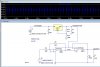
I have built a full wave active bridge circuit which forms part of a bigger circuit, but am having problems with the regulated power supply which as can be seen is noisier than the unregulated!!
I don't know what I've got wrong...
 

Attachments

  • screenshot.jpg
    screenshot.jpg
    90.6 KB · Views: 197
  • FullPeak1-2.asc
    3 KB · Views: 158
I think it is just the switching of the 258 into the big cap. You can reduce it by using a better cap than a generic for the bypass after the regulator.
 
The LM317 needs a minimum load of 10mA. But your 470 ohm resistor draws a current of only 2.7mA and the two low-power opamps draw less than 0.6mA.
Your 470 ohm resistor is supposed to be 120 ohms for an LM317 or 240 ohms for a more expensive LM117 (then the 1.8k resistor must also be reduced).
 
The LM317 needs a minimum load of 10mA. But your 470 ohm resistor draws a current of only 2.7mA and the two low-power opamps draw less than 0.6mA.
Your 470 ohm resistor is supposed to be 120 ohms for an LM317 or 240 ohms for a more expensive LM117 (then the 1.8k resistor must also be reduced).

I have dropped the 470 Ohm to 120 Ohm and the 1.8K to 470 Ohm and also tried reducing the big cap down to 1 microfarad and it's still the same (albeit less).

I have noticed that the instability aligns with the cycle of the input sine wave, and every time there is a input peak - either pos or neg, then the supply line develops noise, but don't know why?

Attached screenshot shows this.
 

Attachments

  • screenshot2.jpg
    screenshot2.jpg
    68.2 KB · Views: 181
Last edited:
You say that you built a circuit but instead of an oscilloscope trace you show a simulation. Maybe the sim program doesn't know all the details.

The input to the LM317 shows high frequency noise since the horizontal time is stretched out much too long. But when the horizontal time is decreased 100 times then it shows a small low frequency sine-wave that the LM317 should be able to reduce to almost nothing.
Yes it is stretched, so that you can see the similarity between the frequency of the input sine, and the distortion that is occuring in power supply.
The distortion is showing in the sim at 300mV p-p, and the peak power drawn through the regulator is 30mA peak, which is well within the limits imposed by the LM317. So why doesn't the LM317 reduce this to almost nothing?
Are you suggesting that in practice that this distortion will not occur - just in the sim?
 
C4 is nowhere near big enough. Re-run your sim with 1000uF in place of the 1uF. What you are seeing is the LM317's feeble attempt at recovering to a sudden increase/decrease in its load.

The root cause of your problem is the 47uF capacitor at the output that must be charged in nearly zero time...

To turn this into a practical circuit, make the 47uF capacitor like 0.47uF, and follow that with a voltage follower opamp. Then the bypass on the LM317 can be a "normal" size, like 4.7uF.
 
Last edited:
If you change the resistors per AG then change C4to a 15ufd. tantulum, T520D156M025ASE089 in the cap guide in LT Spice, the "noise" will drop to about 5 mv. It is caused because the 258 turns on at the peak of the sine wave to recharge the output cap. This transistion is a little to fast for the 317 so must be absorbed by the output filter.
 
Another simple fix, at least in the simulation, is to add 10 ohms in series with the 47uF output cap.
 
Status
Not open for further replies.

New Articles From Microcontroller Tips

Back
Top