Hello Everyone,
Project I currently working is about a power supply for powering X-Ray tube. I would like to get more information about this topic and some help from you guys, if you are so kind. I apologize for my bad English.
So, my goal is to build a power supply with max. output voltage 100 - 120 kV with power of 80 W. Voltage should be adjustable (ideally from 0V but it can be from 20 kV or so), but it does not have to be regulated (it would be great anyway).
I have transformers FLYPVM400 from this site https://www.amazing1.com/transformers.html, so i designed Half-bridge driver for it.
**broken link removed**
**broken link removed**
It's using IC SG3525 with adjustable frequency and duty cycle. I also prepared feedback compensation parts, but they are not mounted yet, so values of R14, R15 and C11 are not critical.
Remote pin is for switching the the supply On/Off by external voltage.Whole IC part of the driver will be powered from SMPS Mean Well S-60-12 **broken link removed**
Power part of the supply is connected to Mains Voltage (230 V in our country) by this filter from ATX power supply.
**broken link removed**
I made Gate-Drive Transformer for switching MOSFETs (IRF730). It's wound by 3 twisted enameled copper wire (0,4 mm diameter) on white toroid core (26mm diameter, I dont know exact type of material, but its working so... It's probably from feroxxcube). 36 Turns working just fine (I tested many different core shapes, materials, winding techniques and number of Turns, but this one has best results, but not ideal).
One of Gate-Source voltage waveforms is on this picture.
**broken link removed**
For power transformer, I wound 90 turns with 0,7 mm diameter enameled copper wire. FLYPVM400 has secondary 4000 turns. I measured this voltage waveforms with HV scope probes. Yellow is primary, blue is secondary.
**broken link removed**
Here, first issue appears. Why is there sinusoidal waveform on secondary? Is it influence of parasitic capacitance between secondary turns or leakage inductance of transformer? There is also significant voltage drop on primary waveform. Rectified 230V is about 310Vdc and measured primary voltage waveform aplitude is about 280V. Why is that so?
Amplitude of sinusoidal waveform is dependent on switching frequency. (more Hz - less Voltage) so im using this for adjusting output voltage. Also rectifired output Vdc voltage is dependent on freqeuncy and independent on duty cycle. Realy weird for me =/
FLYPVM400 has rating of 20 kV on output. For getting higher voltage i'm using villard cascade multiplier with 10 stages. Capacitors are 1nF / 30 kV (**broken link removed**) and diodes are 20kV / 10 mA (**broken link removed**) Whole Multiplier is in epoxy.
**broken link removed**
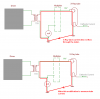
Whole high voltage part (transformer, multiplier) including x-ray tube is in lead box isolated also by epoxide and filled with insulating oil. I conected whole thing like this:
**broken link removed**
Is it posible to measure current through x-ray tube like that? Is there better option?
I measured voltage with multimeter HV probe. System worked good, I also made few pictures with dental x-ray tube.
**broken link removed**
But then, multiplier crashed at 60 kV and 1mA (two multipliers crashed like that) under the load. After crash, theres only small voltage on the output of multiplier (6 kV - 9 kV).
How can I measure ripple on High DC voltage? When im using resistive divider from HV resistors and scope probe i get distorted results (realy huge ripple).
If anyone has any idea or remarks for any part of my project, please, let me know. Thank you all for reading. Posting some feedback would be great.
Project I currently working is about a power supply for powering X-Ray tube. I would like to get more information about this topic and some help from you guys, if you are so kind. I apologize for my bad English.
So, my goal is to build a power supply with max. output voltage 100 - 120 kV with power of 80 W. Voltage should be adjustable (ideally from 0V but it can be from 20 kV or so), but it does not have to be regulated (it would be great anyway).
I have transformers FLYPVM400 from this site https://www.amazing1.com/transformers.html, so i designed Half-bridge driver for it.
**broken link removed**
**broken link removed**
It's using IC SG3525 with adjustable frequency and duty cycle. I also prepared feedback compensation parts, but they are not mounted yet, so values of R14, R15 and C11 are not critical.
Remote pin is for switching the the supply On/Off by external voltage.Whole IC part of the driver will be powered from SMPS Mean Well S-60-12 **broken link removed**
Power part of the supply is connected to Mains Voltage (230 V in our country) by this filter from ATX power supply.
**broken link removed**
I made Gate-Drive Transformer for switching MOSFETs (IRF730). It's wound by 3 twisted enameled copper wire (0,4 mm diameter) on white toroid core (26mm diameter, I dont know exact type of material, but its working so... It's probably from feroxxcube). 36 Turns working just fine (I tested many different core shapes, materials, winding techniques and number of Turns, but this one has best results, but not ideal).
One of Gate-Source voltage waveforms is on this picture.
**broken link removed**
For power transformer, I wound 90 turns with 0,7 mm diameter enameled copper wire. FLYPVM400 has secondary 4000 turns. I measured this voltage waveforms with HV scope probes. Yellow is primary, blue is secondary.
**broken link removed**
Here, first issue appears. Why is there sinusoidal waveform on secondary? Is it influence of parasitic capacitance between secondary turns or leakage inductance of transformer? There is also significant voltage drop on primary waveform. Rectified 230V is about 310Vdc and measured primary voltage waveform aplitude is about 280V. Why is that so?
Amplitude of sinusoidal waveform is dependent on switching frequency. (more Hz - less Voltage) so im using this for adjusting output voltage. Also rectifired output Vdc voltage is dependent on freqeuncy and independent on duty cycle. Realy weird for me =/
FLYPVM400 has rating of 20 kV on output. For getting higher voltage i'm using villard cascade multiplier with 10 stages. Capacitors are 1nF / 30 kV (**broken link removed**) and diodes are 20kV / 10 mA (**broken link removed**) Whole Multiplier is in epoxy.
**broken link removed**
Whole high voltage part (transformer, multiplier) including x-ray tube is in lead box isolated also by epoxide and filled with insulating oil. I conected whole thing like this:
**broken link removed**
Is it posible to measure current through x-ray tube like that? Is there better option?
I measured voltage with multimeter HV probe. System worked good, I also made few pictures with dental x-ray tube.
**broken link removed**
But then, multiplier crashed at 60 kV and 1mA (two multipliers crashed like that) under the load. After crash, theres only small voltage on the output of multiplier (6 kV - 9 kV).
How can I measure ripple on High DC voltage? When im using resistive divider from HV resistors and scope probe i get distorted results (realy huge ripple).
If anyone has any idea or remarks for any part of my project, please, let me know. Thank you all for reading. Posting some feedback would be great.