happybenguy
New Member
hi everyone, I was just pondering somthing the other day...
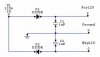
How come all the amps i've seen have a transformer in their power supply? I have a schematic of a powersupply i think would work below, but I dont wanna try it until i know why they use transformers instead of just making a +120 and -120 volt rails strait from the outlet. Is the voltage level the only deciding factor for using a transformer? I was just wounderin because high powered transformers seem to be big and expensive so i figured maybe this would work instead....
let me know what you guys think!
p.s. I know the capacitors would have to be sized differently, but i used those just for example.