Continue to Site

Welcome to our site!

Electro Tech is an online community (with over 170,000 members) who enjoy talking about and building electronic circuits, projects and gadgets. To participate you need to register. Registration is free. Click here to register now.

  • Welcome to our site! Electro Tech is an online community (with over 170,000 members) who enjoy talking about and building electronic circuits, projects and gadgets. To participate you need to register. Registration is free. Click here to register now.

Power supply circurt will it work?!?

Status
Not open for further replies.

tkc100

Member
I have posted another thread on a very similar subject but I’m afraid it became too twisted. I asked too many questions and started out with some wrong information. I’m sure I confused everyone.
So I will make this brief and to the point.
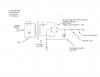
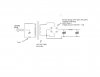
Will the attached circuit work?
I need an out put of 15 + volts at 25 amps
Can anyone assist me with these calculations?
What would my final output voltage be?
What should the value for the capacitor be to achieve 10 % ripple?
Sorry for all the mental twists and confusion.
Thank you all for you help!
 

Attachments

  • Charging Circurt Diagram.jpg
    Charging Circurt Diagram.jpg
    107.9 KB · Views: 211
Well, again, we need more information.

How much current is this expected to deliver? (I can see a 30-amp circuit breaker: does that mean you want it to be able to deliver 25 amps continuously? 30 amps peak?)

Can't size the filter capacitor until we know that; then you can calculate it to get no more than 10% ripple.

And why do you have that resistor in there?

Yes, it'll work: at least, it looks as if it won't blow up when you plug it in, and it'll probably deliver DC to the load. But as to whether it's suitable for your application, still can't really tell.

Why do you show a "heat sink" as a component in series with the primary? Generally speaking, heat sinks aren't shown as parts of schematics (possibly as notes). What is that exactly--another thermal fuse?
 
25 amps
The breaker is a fail safe at 30 amps
The resistor is in series with the secondary winding to control the current output to 25 amps
T-1, T-2 and T-3 are thermal switches (heat-sink, chassis and transformer) are their location.
 
It looks like you're going to need a mighty big capacitor there.

Quick formula from my electronics textbook for minimum capacitance, given allowable ripple and load resistance:

Cmin = 0.24/(r * Rl)

where r is the ripple factor. (%).

Since you're running 15V @ 25A, your load resistance is 0.6 ohms.

Plugging this in gives a result of ... 4 farads. As in farads, not microfarads.
 
You may like to put an inductor in place of the 0R6 resistor. This will reduce your capacitance considerably - by using a capacitor-inut pi filter. The only thing to do is buy the largest inductor possible or wind one yourself and start with 10,000u x 2 on the input and 10,000u x 2 on the output. Load the power supply and view the waveform on a CRO. You can also buy 100,000u but they are much more expensive.
The inductor gives you the maximum possibilities as you have about 5v - 6v to play with.
 
Last edited:
If I've understood the requirements correctly then unfortunately the circuit won't give the desired output. The peak no-load voltage on the cap is 16.4 * 1.414 - 2.2 = 21V. If the load draws 25A then the voltage drop across the 0.6 ohm resistor is 0.6 * 25 = 15V. So the voltage across the load is never more than 21 - 15 = 6V; not the required 15V. Moreover, no allowance has been made for the transformer regulation. The voltage drop due to the transformer winding resistance will result in an even lower load voltage.
IMHO for the required output it would be much cheaper and more efficient to use an SMPS rather than this circuit.

Alec
 
A 25 amp SMPS is way beyond his capabilities. Wait until he replies to my suggestion of a pi filter.
 
Thank you all so much for all the input.
I may have misspoken or probably don’t understand the ripple voltage.
In plain words, I need a relatively clean output, not perfect. This power supply will be, feeding through a charge controller and then into a battery bank. The charge controller is a PWM controller and I’m not sure how clean its input must be. I really hesitate to even mention these facts because in previous threads it all got too confusing. Surely something less than 4farads (I’ve never even seen such a thing) is workable. My calculations, and I’m saying this with no authority is somewhere between 10,000 and 13,000 µf with a working voltage of 50 volts.

As far as using an inductor, sounds interesting but I would be totally dependent on your help because that goes beyond my level of expertise.
Please feel free to add subtract or change it anyway you all feel will work. In the end I need 15.3 volts (there is a .3 volt loss across the controller) with a controlled current output of 25 amps. Don’t get hung on the 15.3 volts. I need a minimum of 15.3 volts but could make do with any thing up to 55 volts. The voltage need not be controlled but I think the current needs to be.

I put the .6 ohm resistor in the circuit in an attempt to control the current flow to 25 amps from the transformer. A deeply discharged battery will take all the transformer can produce and I’m afraid without some sort of regulation it will smoke. This may not or very possibly is not the best way to do it.

colin55 you are probably right a switched mode power supply is more than likely beyond my level. I am a good tinker and a good project builder but not an electrical engineer.
I rely heavy on you all and your experience when I get myself is a spot such as this.
I am trying to use some parts and pieces I have got and if the cost exceeds a 150 of so dollars then it is no longer feasible. I can buy an Iota three stage charger for around $200.
I haven’t got that right now and I am sure tired of monitoring my battery bank but I don’t think it would make sense to dump too much into it.
So the challenge is can it be made to work? I am learning a lot and look forward to your responses.
Thanks!
 
If you are charging batteries, you don't need any filtering at all and the more ripple the better. Just send the rectified voltage into the battery and monitor the charge with a hydrometer. Put the 0.6 ohm in circuit at the beginning to limit the current. It can be 4 x 50 watt old car lamps in series/parallel
 
collin55
There is one piece between the two. A PMW charge controller and it has a lot of circuitry. It will handle monitoring the SOC but I don’t know how sensitive its circuitry is. That is the reason I had hoped to smooth it out a bit. I didn’t mention it is the original post because of a previous thread I had started. Too much of the discussion was around the controller and charging batteries and that is not what I needed help with.
Is the resistor in the wrong place?
What about your idea of using an inductor. You got my curiosity peaked.
What do you think about alec_t comment? Is it possible to make this work?
I appreciate the attempt at economy but I can afford a resistor and would like to make something that is at least semi-finished.
Thanks for the input!!!
 
If you have 16.4 volts RMS then there is more to work with. Depending on the resistance of the transformer 3 or 4 of these guys would give you about 17 volts minimum. 66,000 - 88000 Ufd. total.
https://www.electro-tech-online.com/custompdfs/2011/07/SLPX.pdf
I think I would trust the controller to protect the bulk supply and get rid of all the thermal sensors just keeping the fuse.
If you have specs on the transformer and controller it would help to make sure thinks are ok.
 
Here's your capacitor-input pi filter:

**broken link removed**

In case you were wondering, it's called that because it looks like the Greek letter pi (lowercase).

Component values TBD.
 
You have to know if the controller takes raw AC, pulsed DC or requires some sort of smoothing. I don't think it will need any smoothing at all.
 
Ok! carbonzit
Is this what you had in mind (see attachment)
Will I still need a resistor in series with the transformer's secondary to control the current output?
colin55 ronv Attached is the data sheet for the controller. I have the entire manual but it does not go into any more detail about the internal working of the unit. I doubt that Xantrex will part with a schematic.
The 16.4 volts is a RMS value. My DMM reads true RMS values.
I think it is starting to happen thanks.
I have got to sign off for the night will check in in the morning.
 

Attachments

  • Charging Circurt Diagram update.jpg
    Charging Circurt Diagram update.jpg
    74.4 KB · Views: 164
  • C Series Controllers Data Sheet.jpg
    C Series Controllers Data Sheet.jpg
    311.3 KB · Views: 173
That's it.

If you're going to use a charge controller then you don't have to worry about limiting the current; the controller should do that. (The inductor will limit the current somewhat, as it has a little resistance.)
 
The output from the 4 diodes will become smoothed DC once the controller is connected and delivering current to the battery.
You don't need any smoothing or filtering or current-limiting components.
 
carbonzit & colin55
As stated in a previous post I rely heavily on individuals such as yourselves when I get in over my head. I do not have a great deal of practical knowledge when it comes to the actual design and function of electronic components but I do have experience with alternative energy sources, especially solar. That is why it is not just by chance that I happen to have a charge controller on hand.
I know from actual experience that the charge controller monitors the batteries SOC merely by adjusting the voltage. Rarely, in a solar system do you have too much current. In fact that would be a pleasant thing to have to deal with. So there is little or no reason for the designer of such equipment to concern themselves with that. When a lead acid battery is deeply discharged the counter voltage seen by the power supply is low and the battery will accept all the current available. For all practical purposes it appears almost as a dead short. I know that it’s not but suffice to say the battery will attempt to take on all that can be thrown at it. If there is too much current available, again this is never a problem with a solar array the battery will do harm to itself. When the battery is in this state the controller will go into what is called bulk charging mode and with the particular controller deliver up to 60 amps continuously, 85 amps before shut down. Way to much for my battery bank as it is currently configured. My battery bank needs no more than 25 amps to safely charge.
So I think you will see I am attempting to use a piece of equipment out of context. I have a solar array but it’s not functioning properly right now so I have been living off a generator. It is a Honda 2000i rated at 120 VAC at 13 amps. Actually it would be to my advantage to be able to charge off this generator even when funds are available and the solar array is back up and running.
I am hoping to provide a power supply to the controller that will not damage it or the batteries.
The linear power supply we have been discussing will without some sort of restraint attempt to deliver all the current it can until it smokes something, most probably the transformer.
As to the issue of how smooth the DC output needs to be, I’m only guessing. I have had no luck getting an informed response from Xantrex. It seems impossible to get to the actual engineers and the technical support people are not equipped to answer such questions. I do know the controller was designed to operate with solar, (which is pure DC), wind, (which is most often rectified AC) and hydro (which can come in either flavor). I though of erring on the safe side and smoothing things out a bit. Also isn’t actual output voltage a little higher when the DC ripple is smoothed out somewhat?
So what do you all think?

If I am to go the route of using an inductor I will need some help with the component values.
To limit the power supplies’ output will I still need to place a resistor in series with the secondary output? Where would it be placed? Is .6 ohms the correct value?

Finally will I be able to attain an output of 15.3 volts? Actually I could get by with a little less. It takes 15 volts to equalize a battery back such as the one I have and there is a .3 volt loss over the controller. This is a maintenance function, performed about once a month. I have other means of doing that but I do need 14.3 volts to properly charge the batteries. Perhaps this is the first and most important question because if too much is lost as alec_t alluded to in post #7 then all the other brain damage is without purpose.
alec_t have you any other thoughts on this matter.
At the very least I have learned a great deal and I can’t begin to tell you all how grateful I am for your support.:)
 
The simpest thing to do is get a 12v battery and connect it to the output of the bridge. Now get a 2 or 3 NiCd rechargeable cells and put them in parallel and add them to the 12v battery. You now have a (12.6v plus 1.2v) capacitor at many Farads to act an input for your controller.
This will fix your problem and you don't have to ask any more questions.
 
When I read about the charge controller it states the bulk charge and float voltage are adjustable. This makes a lot of sense because they don't know what battery is being charged so they give you a way to limit bulk current and float voltage so you don't ruin the battery. I would just add the caps (about $15), set the bulk charge rate for your battery (usually C/10). So if you have a 100 amp hour battery set the bulk to 10 amps, 150 amp hour, 15 amps etc. The charge controller will then limit the maximum current, so no resistors are necessary.
Yes the capacitors will charge, with no load, to 1.4 times the RMS voltage.
Let us know if the controller doesn't work that way.
Battery type, capacity and chemistry might also be good. I'm assuming it's a big old lead acid deep cycle.
Collin may be right and you don't need any smoothing or the controller may not like to see it's input voltage drop to zero in between peaks. But the smoothed input can't hurt.
I don't think I would try to make a 25 amp inductor, just the caps.

Edit:
More reading.... You can't limit the bulk charge current only the voltage so you do need something to limit the current. Can you measure the resistance of your transformer so we can get an idea of how much more is needed.
 
Last edited:
Status
Not open for further replies.

Latest threads

New Articles From Microcontroller Tips

Back
Top