Electro Tech is an online community (with over 170,000 members) who enjoy talking about and building electronic circuits, projects and gadgets. To participate you need to register. Registration is free. Click here to register now.
Welcome to our site! Electro Tech is an online community (with over 170,000 members) who enjoy talking about and building electronic circuits, projects and gadgets. To participate you need to register. Registration is free. Click here to register now.
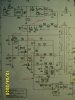
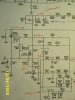
Here are 2 photos of the relevant part of the Circuit.
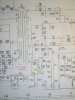
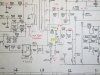
I presume that the starting string is the 5 resistors of 220k. I measured them in circuit and all are correct.
I replaced CP011, CP025, CP031, CP032 & CP040 as they all had high ESR, but to no avail.
The only issue found so far is that RP028 and RP030 are 15 <a href="#">ohm</a> when I measured them in circuit with an Ohmmeter. So one or both must be high.
Thanks Nigel,
I put a short across the ends of the 220k resistor string (they are surface mounted resistors) to measure them.
This eliminated the vaguries due to the supply impedance. Across each resistor I measured about 176k which is correct (220k // 880k). (4 resistors in series across one)
To measure RP028 and RP030, I oriented the meter so the CB junction of TP022 would be reverse biassed.
in tv, the faults maybe in regulator or horizontal output transistor. there are also faults that the over current protection and over voltage protection kick-on.
If horizontal output transistor is good the fault maybe in regulator circuit which drive the switching transformer.
in feedbak circuit, try to check the opto-isolator/relay.
This site uses cookies to help personalise content, tailor your experience and to keep you logged in if you register.
By continuing to use this site, you are consenting to our use of cookies.